KPCMCIA-12AIAOH User’s Manual
I/O Registers
C-19
Auxiliary control register (base + 15, write only)
This register configures the operation of A/D, D/A, and the timer counter. It is 8-bit wide and
write only.
Refer to Table C-18. Bit 7 selects between TTL and analog trigger source. Bit 6 sets the pre-
trigger option. Refer to Section 3 and “Analog trigger threshold” in this section for further
information.
Bit 5 is for the timer/counter interrupt control. Bits 3 and 4 determine the timer/counter operation
modes, while bit 2 selects its clock source. Refer to Section 3 and “Timer/counter port (base +10,
base +11)” in this section for more information.
Bits 1 and 0 specify the D/A update modes. Refer to Section 3 and “D/A update modes” in this
section for more information.
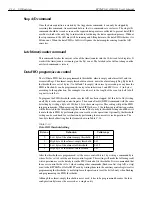
Table C-18
Auxiliary control register bit definitions
Bit
Function
Explanation
7
External trigger source
0 selects TTL trigger
1 selects analog trigger
6
Pre-trigger option
1 = with pre-trigger, 0 = without
5
Timer/counter interrupt
Clear overflow event latch
1 = Enabled, 0 = Disabled
by writing 0 into this bit
4,3
Timer/counter mode
00 = Reload
01 = Pause
10 = Go
11 = Go/Pause by external gate signal
2
Timer/counter clock source
1 = External, 0 = Internal (1MHz)
1,0
D/A update mode
00 = Direct update
01 = When timer/counter overflows
10 = When ext. gate goes low to high
11 = When pacer clock fires
Summary of Contents for KPCMCIA-12AIAOH
Page 11: ...1 Introduction...
Page 15: ...2 Installation...
Page 17: ...3 Theory of Operation...
Page 25: ...4 I O Connections...
Page 28: ...5 Optional Accessories...
Page 30: ...A Specifications...
Page 33: ...B PCMCIA Interface...
Page 36: ...C I O Registers...


