Chapter 4
28
Wiring Signals to the BNC Connectors
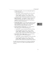
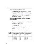
To wire signals using the BNC connectors, connect the appropriate
BNC connector to the appropriate input/output using a BNC cable.
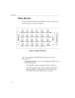
The KUSB-3116 module, shown in
, contains 24
BNC connectors (16 BNC connectors for single-ended analog inputs,
four BNC connectors for analog outputs, and four BNC connectors
for external clocks and triggers).
Wiring Signals to the D-Sub Connectors on the BNC
Connection Box
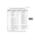
If you do not want to use the BNC connectors or if you want to
connect digital I/O or counter/timer signals to the KUSB-3116
module, you can use the 37-pin, D-sub connectors. These connectors
are described in the following sections.
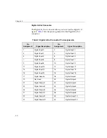
Analog Input Connector
The Analog Input connector allows you to access the analog input
signals.
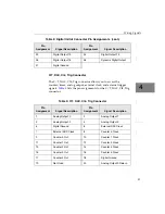
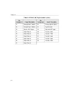
lists the pin assignments for the analog input
connector.
Table 1: Analog Input Connector Pin Assignments
Pin
Assignment
Signal Description
Pin
Assignment
Signal Description
1
Analog Input 0
2
Analog Input 1
3
Analog Input 2
4
Analog Input 3
5
Analog Input 4
6
Analog Input 5
7
Analog Input 6
8
Analog Input 7
9
Analog Input 8
10
Analog Input 9
Summary of Contents for KUSB-3116
Page 10: ...Contents x...
Page 14: ...About this Manual xiv...
Page 15: ...1 1 Overview Hardware Features 2 Supported Software 4 Getting Started Procedure 5...
Page 20: ...Chapter 1 6...
Page 26: ...Chapter 2 12...
Page 64: ...Chapter 4 50...
Page 65: ...51 5 Verifying the Operation of a Module Overview 53 Running the Quick Data Acq Application 54...
Page 75: ...61 A Ground Power and Isolation Connections...
Page 78: ...Appendix A 64...
Page 82: ...Index 68...


