background image

Chapter 5

54

Running the Quick Data Acq Application

To run the Quick Data Acq


application, perform the following steps:

1.

If you have not already done so, power up your computer and 
any attached peripherals.

2.

Select 

Quick Data Acq

 from the Keithley Instruments\Quick 

Data Acq program group.

Note:

The Quick Data Acq application allows you to verify basic 

operations on the module; however, it may not support all of the 
module’s features. For information about each of the supported 
features, use the online help for the Quick Data Acq application by 
pressing 

F1

 from any view or selecting the 

Help

 menu, or refer to the 

KUSB-3116 User’s Manual

.

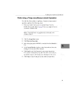
Performing a Single-Value Analog Input Operation

To verify that the module can read a single analog input value, 
perform the following steps:

1.

Connect a voltage source, such as a function generator, to analog 
input channel 0 (differential mode) on the KUSB-3116 module. 
Refer to 

page 37

 for an example of how to connect a differential 

analog input.

2.

Click the 

Acquisition

 menu.

3.

Click 

Single Analog Input

.

4.

Select the appropriate KUSB-3116 module from the 

Board

 list 

box. 

5.

In the 

Channel

 list box, select analog input channel 0.

6.

In the 

Range

 list box, select the range for the channel. The default 

is ±10 V. 

Summary of Contents for KUSB-3116

Page 1: ...www keithley com A G R E A T E R M E A S U R E O F C O N F I D E N C E KUSB 3116 Getting Started Manual KUSB3116 903 01 Rev A January 2005...

Page 2: ...cation without Keithley s express written consent or misuse of any product or part This warranty also does not apply to fuses software non rechargeable batteries damage from battery leak age or proble...

Page 3: ...KUSB 3116 Getting Started Manual 2005 Keithley Instruments Inc All rights reserved First Printing January 2005 Cleveland Ohio U S A Document Number KUSB3116 903 01A Rev A...

Page 4: ...rate immediately into the manual Addenda are numbered sequentially When a new Revision is created all Addenda associated with the previous Revision of the manual are incorporated into the new Revision...

Page 5: ...that a shock hazard exists when voltage levels greater than 30V RMS 42 4V peak or 60VDC are present A good safety practice is to ex pect that hazardous voltage is present in any unknown circuit before...

Page 6: ...lectric shock and fire replacement components in mains circuits including the power transformer test leads and input jacks must be purchased from Keithley Instru ments Standard fuses with applicable n...

Page 7: ...arted Procedure 5 Chapter 2 Preparing to Use a Module 7 Unpacking 9 Checking the System Requirements 10 Installing the Software 11 Chapter 3 Setting Up and Installing a Module 13 Applying Power to the...

Page 8: ...cting Digital I O Signals 42 Connecting Counter Timer Signals 43 Connecting Signals for Event Counting Operations 43 Connecting Signals for Up Down Counting Operations 45 Connecting Signals for Freque...

Page 9: ...lue Digital Input Operation 57 Performing a Single Value Digital Output Operation 58 Performing a Frequency Measurement Operation 59 Performing a Pulse Output Operation 60 Appendix A Ground Power and...

Page 10: ...Contents x...

Page 11: ...is Organized This manual is organized as follows Chapter 1 Overview describes the key features of the KUSB 3116 hardware and software and provides an overview of the getting started procedure Chapter...

Page 12: ...strophic damage to yourself or your equipment Items that you select or type are shown in bold Courier font is used to represent source code Related Information Refer to the following documents for mor...

Page 13: ...sual C DT LV Link Getting Started Manual This manual describes how to use DT LV LinkTM with the LabVIEW graphical programming language to access the capabilities of your module Microsoft Windows 2000...

Page 14: ...About this Manual xiv...

Page 15: ...1 1 Overview Hardware Features 2 Supported Software 4 Getting Started Procedure 5...

Page 16: ...ut ranges of 10 5 2 5 and 1 25 V 1024 location channel gain list You can cycle through the channel gain list using continuous scan mode or triggered scan mode The maximum sampling rate when using the...

Page 17: ...mic digital output line that changes state whenever an analog input channel is read Five 32 bit counter timer C T channels that perform event counting up down counting frequency measurement edge to ed...

Page 18: ...running Using the Quick Data Acq application you can verify the features of the module display data on the screen and save data to disk DataAcq SDK This DT Open Layers Software Develop Kit SDK allows...

Page 19: ...apter the shaded area in the diagram shows you where you are in the getting started procedure Figure 1 Getting Started Flow Diagram Set Up and Install the Module see Chapter 3 starting on page 13 Wire...

Page 20: ...Chapter 1 6...

Page 21: ...7 2 Preparing to Use a Module Unpacking 9 Checking the System Requirements 10 Installing the Software 11...

Page 22: ...Up and Install the Module see Chapter 3 starting on page 13 Wire Signals see Chapter 4 starting on page 23 Verify the Operation of the Module see Chapter 5 starting on page 51 Prepare to Use the Modu...

Page 23: ...box and verify that the following items are present KUSB 3116 BNC module USB cable Power supply Keithley CD If an item is missing or damaged contact Keithley Technical Support Once you have unpacked y...

Page 24: ...In addition for some systems you may have to disable standby mode If you are not sure whether you are using USB Ver 1 1 or Ver 2 0 run the Open Layers Control Panel applet described on page 16 One or...

Page 25: ...appears 3 In the Command Line edit box enter D Setup Exe If your CD ROM is not in drive D enter the letter of the drive where your CD ROM is located The welcome screen appears 4 Click Install Drivers...

Page 26: ...Chapter 2 12...

Page 27: ...13 3 Setting Up and Installing a Module Applying Power to the Module 15 Configuring the Device Driver 16 Attaching Modules to the Computer 18...

Page 28: ...her adjustment prior to installation Set Up and Install the Module this chapter Wire Signals to the BNC Connection Box see Chapter 4 starting on page 23 Prepare to Use the Module see Chapter 2 startin...

Page 29: ...16 module perform the following steps 1 Connect the 5 V power supply to the power connector on the KUSB 3116 module Refer to Figure 2 Figure 2 Attaching a 5 V Power Supply to the Module 2 Plug the pow...

Page 30: ...on the module This ensures that 10 k of bias return termination resistance is used for the analog input channels This is the default configuration Bias return termination resistance is particularly u...

Page 31: ...3 3 3 3 3 3 3 3 3 10 Repeat steps 4 to 8 for the other modules that you want to configure 11 Close the Data Acquisition Control Panel dialog box Continue by connecting the KUSB 3116 module to the comp...

Page 32: ...you wish without causing damage This process is called hot swapping Your application may take a few seconds to recognize a module once it is plugged back in Connecting One or Two Modules To connect on...

Page 33: ...s Click Next to have the wizard search for the device driver then proceed to step 5 5 Click the option to search for the driver then click Next 6 Click the option to specify the location browse to the...

Page 34: ...at you can connect to a single USB port To connect multiple KUSB 3116 modules to an expansion hub perform the following steps 1 Make sure that you have attached a power supply to the module 2 Attach o...

Page 35: ...search for the driver then click Next 7 Click the option to specify the location browse to the location on the CD that contains the driver files then click Next 8 Click Next 9 Click Finish A New Hard...

Page 36: ...attached the number of expansion hubs up to five and modules up to four per hub that you require The operating system automatically detects the USB devices as they are installed Continue with the inst...

Page 37: ...23 4 Wiring Signals Preparing to Wire Signals 25 Connecting Analog Input Signals 33 Connecting Analog Output Signals 41 Connecting Digital I O Signals 42 Connecting Counter Timer Signals 43...

Page 38: ...et Up and Install the Module see Chapter 3 starting on page 13 Wire Signals this chapter Verify the Operation of the Module see Chapter 5 starting on page 51 Prepare to Use a Module see Chapter 2 star...

Page 39: ...ate power and signal lines by using physically different wiring paths or conduits To avoid noise do not locate the box and cabling next to sources that produce high electromagnetic fields such as larg...

Page 40: ...gnals in one of the following ways Using the BNC connectors labelled AD Ch0 to AD Ch15 Using the appropriate pins on the Analog Input connector Refer to Appendix A in the KUSB 3116 User s Manual for i...

Page 41: ...ix A in the KUSB 3116 User s Manual for information about the required mating connectors External A D clock or trigger signal You can wire external clock trigger signals in one of the following ways U...

Page 42: ...u do not want to use the BNC connectors or if you want to connect digital I O or counter timer signals to the KUSB 3116 module you can use the 37 pin D sub connectors These connectors are described in...

Page 43: ...26 Analog Input 6 Return Analog In 14a 27 Analog Input 7 Return Analog In 15a 28 Analog Input 8 Returna 29 Analog Input 9 Returna 30 Analog Input 10 Returna 31 Analog Input 11 Returna 32 Analog Input...

Page 44: ...gital Input 3 5 Digital Input 4 6 Digital Input 5 7 Digital Input 6 8 Digital Input 7 9 Digital Input 8 10 Digital Input 9 11 Digital Input 10 12 Digital Input 11 13 Digital Input 12 14 Digital Input...

Page 45: ...DAC Clk Trig Connector Pin Assignment Signal Description Pin Assignment Signal Description 1 Analog Output 0 2 Analog Output 1 3 Analog Output 2 4 Analog Output 3 5 Digital Ground 6 External DAC Cloc...

Page 46: ...r 26 External ADC Trigger 27 Digital Ground 28 Counter 0 Gate 29 Digital Ground 30 Counter 1 Gate 31 Digital Ground 32 Counter 2 Gate 33 Digital Ground 34 Counter 3 Gate 35 Digital Ground 36 Counter 4...

Page 47: ...ge the difference between the ground potentials of the signal source and the ground of the screw terminal panel or between the grounds of other signals exists and the differential configuration is not...

Page 48: ...els 0 and 1 in this case to the BNC connectors on the KUSB 3116 module Figure 6 Connecting Single Ended Inputs to the BNC Connectors Figure 7 shows how to connect single ended voltage inputs channels...

Page 49: ...on the KUSB 3116 module Figure 8 Connecting Pseudo Differential Inputs to the BNC Connectors Screw Terminal Panel Signal Source Vsource 1 1 2 Analog In 0 Analog In 1 Vsource 0 Analog Ground 17 Amp Low...

Page 50: ...and 1 in this case using your own cable screw terminal panel Figure 9 Connecting Pseudo Differential Inputs to a Screw Terminal Panel 1 2 17 36 Signal Source Analog In 0 Analog In 1 VCM Analog Ground...

Page 51: ...differential inputs A floating signal source is a voltage source that has no connection with earth ground Note For floating signal sources it is recommended that you provide a bias return path for the...

Page 52: ...Note that the negative side of the bridge supply must be returned to analog ground Figure 11 Connecting Differential Inputs to a Screw Terminal Panel Floating Signal Source 20 36 Analog In 0 Analog In...

Page 53: ...ide of the signal is connected to ground at the signal source not at the screw terminal panel and do not tie the two grounds together Figure 12 Connecting Differential Voltage Inputs from a Grounded S...

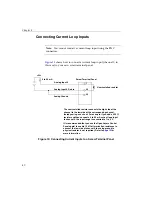
Page 54: ...alled resistor The user installed resistor connects the high side of the channel to the low side of the corresponding channel thereby acting as a shunt For example if you add a 250 resistor and then c...

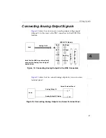
Page 55: ...s to the BNC Connectors Figure 15 shows how to connect analog outputs to your own screw terminal panel Figure 15 Connecting Analog Outputs to a Screw Terminal Panel Load Analog Out 0 Digital I O C T D...

Page 56: ...ting Digital Inputs to a Screw Terminal Panel Figure 17 shows how to connect a digital output line 0 in this case to your own screw terminal panel Figure 17 Connecting Digital Outputs to a Screw Termi...

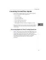
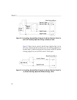
Page 57: ...how to connect counter timer signals Refer to the KUSB 3116 User s Manual for more information about using the counter timers Connecting Signals for Event Counting Operations Figure 18 shows how to c...

Page 58: ...operation on counter timer 0 without using a gate The counter counts the number of rising edges that occur on the Counter 0 Clock input Figure 19 Connecting Counter Timer Signals to a Screw Terminal P...

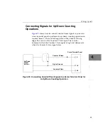
Page 59: ...ter timer 0 The counter keeps track of the number of rising edges that occur on the Counter 0 Clock input The counter increments when the Counter 0 Gate signal is high and decrements when the Counter...

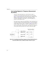
Page 60: ...re accuracy than the Windows timer can provide you can connect a pulse of a known duration such as a one shot output of counter timer 1 to the Counter 0 Gate input Figure 21 shows how to connect count...

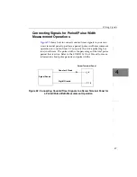
Page 61: ...ation on counter timer 0 You specify the active pulse high or low in software The pulse width is the percentage of the total pulse period that is active Refer to the KUSB 3116 User s Manual for more i...

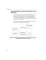
Page 62: ...e start edge in this case a rising edge on the Counter 0 Clock signal and the stop edge in this case a falling edge on the Counter 0 Gate signal You specify the start edge and the stop edge in softwar...

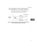
Page 63: ...nal panel to perform a pulse output operation on counter timer 0 in this example an external gate is used Figure 24 Connecting Counter Timer Signals to a Screw Terminal Panel for a Pulse Output Operat...

Page 64: ...Chapter 4 50...

Page 65: ...51 5 Verifying the Operation of a Module Overview 53 Running the Quick Data Acq Application 54...

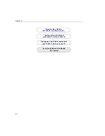
Page 66: ...tall the Module see Chapter 3 starting on page 13 Wire Signals to the BNC Connection Box see Chapter 4 starting on page 23 Verify the Operation of the Module this chapter Prepare to Use a Module see C...

Page 67: ...put channel or digital input port Acquire data continuously from one or more analog input channels using an oscilloscope strip chart or Fast Fourier Transform FFT view Measure the frequency of events...

Page 68: ...k Data Acq application by pressing F1 from any view or selecting the Help menu or refer to the KUSB 3116 User s Manual Performing a Single Value Analog Input Operation To verify that the module can re...

Page 69: ...ter to analog output channel 0 on the module Refer to page 41 for an example of how to connect analog output signals 2 Click the Control menu 3 Click Single Analog Output 4 Select the appropriate KUSB...

Page 70: ...00001 for the display 6 In the Channel list box select analog input channel 1 then click Add to add the channel to the channel list Note that by default channel 0 is included in the channel list 7 Cl...

Page 71: ...or an example of how to connect a digital input 2 Click the Acquisition menu 3 Click Digital Input 4 Select the appropriate KUSB 3116 module from the Board list box 5 Click Get The entire 16 bit digit...

Page 72: ...B 3116 module Refer to page 42 for an example of how to connect a digital output 2 Click the Control menu 3 Click Digital Output 4 Select the appropriate KUSB 3116 module from the Board list box 5 Cli...

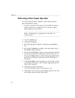
Page 73: ...lock Note The Quick Data Acq application works only with counter timer 0 2 Click the Acquisition menu 3 Click Measure Frequency 4 Select the appropriate KUSB 3116 module from the Board list box 5 In t...

Page 74: ...to output a continuous pulse stream or One Shot to output one pulse 6 Select either Low to high to output a rising edge pulse the high portion of the total pulse output period is the active portion o...

Page 75: ...61 A Ground Power and Isolation Connections...

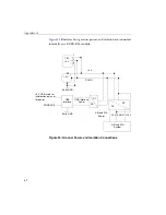
Page 76: ...ernally on a KUSB 3116 module Figure 25 Ground Power and Isolation Connections TB1 5 V 5 V 5 V DGND 1 2 3 Earth GND 5 V USB used for initialization only not for power DGND USB USB Interface USB Interf...

Page 77: ...the BNC connection box You should connect earth ground to the power supply earth You should isolate the 5V DGND input Note that the power supply shipped with the KUSB 3116 module has no connection bet...

Page 78: ...Appendix A 64...

Page 79: ...return resistance 16 37 C cables USB 18 20 configuring the device driver 16 connecting signals analog outputs 41 current loop analog inputs 40 differential analog inputs 37 digital inputs and outputs...

Page 80: ...ion differential analog 33 pseudo differential analog 33 single ended analog 33 installing the software 11 isolation 62 J J2 connector pin assignments 31 L LEDs 18 20 O online help 54 Open Layers Cont...

Page 81: ...signals analog outputs 41 current loop analog inputs 40 differential analog inputs 37 digital inputs and outputs 42 edge to edge measurement 48 event counting 43 frequency measurement 46 methods 26 p...

Page 82: ...Index 68...

Page 83: ...eithley Instruments Inc All other trademarks and trade names are the property of their respective companies A G R E A T E R M E A S U R E O F C O N F I D E N C E Keithley Instruments Inc Corporate Hea...

Reviews: