Appendix A
62
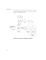
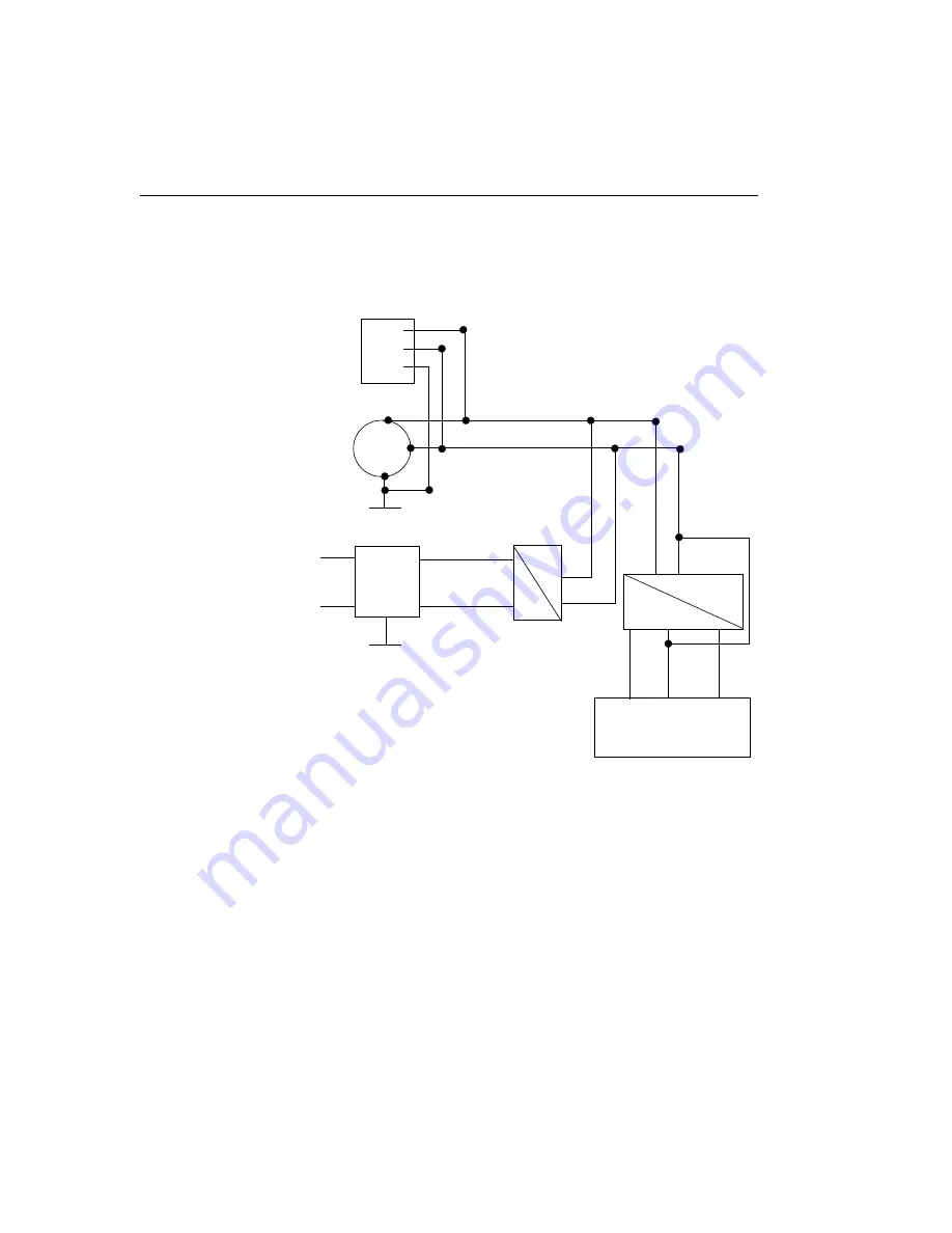
illustrates how ground, power, and isolation are connected
internally on a KUSB-3116 module.
Figure 25: Ground, Power, and Isolation Connections
TB1
+5 V
+5 V
+5 V
DGND
1
2
3
Earth GND
+5 V USB; used for
initialization only, not
for power.
DGND USB
USB
Interface
USB Interface
Power
Earth GND
DC
DC
DC
DC
A/D and D/A
Power
A/D and D/A
System
AGND
-15 V
+15 V
Summary of Contents for KUSB-3116
Page 10: ...Contents x...
Page 14: ...About this Manual xiv...
Page 15: ...1 1 Overview Hardware Features 2 Supported Software 4 Getting Started Procedure 5...
Page 20: ...Chapter 1 6...
Page 26: ...Chapter 2 12...
Page 64: ...Chapter 4 50...
Page 65: ...51 5 Verifying the Operation of a Module Overview 53 Running the Quick Data Acq Application 54...
Page 75: ...61 A Ground Power and Isolation Connections...
Page 78: ...Appendix A 64...
Page 82: ...Index 68...

