4
Wiring Signals
35
4
4
4
4
4
4
4
4
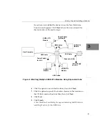
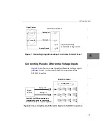
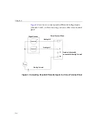
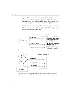
Figure 7: Connecting Single-Ended Inputs to a Screw Terminal Panel
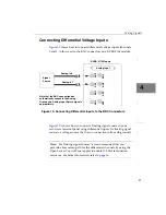
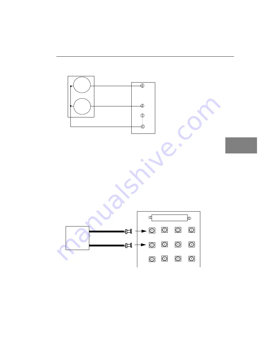
Connecting Pseudo-Differential Voltage Inputs
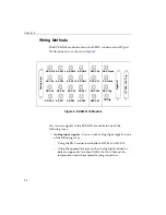
shows how to connect pseudo-differential voltage inputs
(channels 0 and 1, in this case) to the BNC connectors on the
KUSB-3116 module.
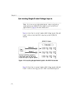
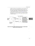
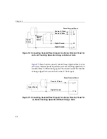
Figure 8: Connecting Pseudo-Differential Inputs to the BNC Connectors
+
Screw Terminal Panel
Signal Source
-
V
source
1
1
2
Analog In 0
+
-
Analog In 1
V
source
0
Analog Ground
17
Amp Low (internally
connected to Analog Ground)
36
Signal
Source
Analog In 0
Analog In 1
AD0
Analog Input
AD1
AD2
AD
6
A
D5
AD
9
AD1
0
AD13
AD14
AD 12
AD8
AD
4
Note that the BNC connection box
automatically connects the Analog
Ground and Amp Low signals together.
KUSB-3116 Module
Summary of Contents for KUSB-3116
Page 10: ...Contents x...
Page 14: ...About this Manual xiv...
Page 15: ...1 1 Overview Hardware Features 2 Supported Software 4 Getting Started Procedure 5...
Page 20: ...Chapter 1 6...
Page 26: ...Chapter 2 12...
Page 64: ...Chapter 4 50...
Page 65: ...51 5 Verifying the Operation of a Module Overview 53 Running the Quick Data Acq Application 54...
Page 75: ...61 A Ground Power and Isolation Connections...
Page 78: ...Appendix A 64...
Page 82: ...Index 68...

