16
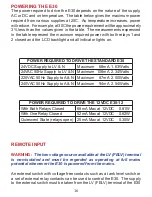
The power required to drive the E30 depends on the nature of the supply,
AC or DC and on temperature. The table below gives the maximum power
required from various supplies at 25C. As temperature increases, power
will reduce. For example, at 30C the power requirement will be approximately
3% less than the values given in the table. The measurements expressed
in the table represent the maximum required power with both relays 1 and
2 closed and the LCD backlight and all indicator lights on.
REMOTE INPUT
WARNING:
The low voltage source available at the LV (FELV) terminal
is non-isolated and must be regarded as operating at full mains
potential whenever the E30 is powered from the mains.
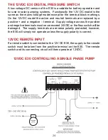
An external switch with voltage free contacts such as a tank level switch or
a set of external relay contacts can be used to control the E30. The supply
to the external switch must be taken from the LV (FELV) terminal of the E30
POWERING THE E30
POWER REQUIRED TO DRIVE THE STANDARD E30
24VDC Supply to LV & N
Maximum 68mA 1.63Watts
24VAC 50Hz Supply to LV & N Maximum 108mA 2.34Watts
220VAC 50Hz Supply to A & N Maximum 87mA 2.00Watts
240VAC 50Hz Supply to A & N Maximum 94mA 2.54Watts
POWER REQUIRED TO DRIVE THE 12VDC E30-12
With Both Relays Closed
68mA Max at 12VDC 0.81W
With One Relay Closed
52mA Max at 12VDC 0.62W
Quiescent State (relays open) 25mA Max at 12VDC 0.30W
Summary of Contents for E30
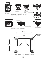
Page 11: ...11 74mm 60mm 4 X 6mm Holes TOP WALL BRACKET DRILL PATTERN...
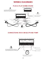
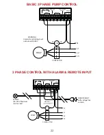
Page 19: ...19 WIRING DIAGRAMS PLUG PLAY CONNECTIONS CONNECTIONS FOR A SINGLE PHASE PUMP...
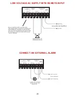
Page 20: ...20 LOW VOLTAGE AC SUPPLY WITH REMOTE INPUT CONNECT AN EXTERNAL ALARM...
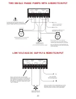
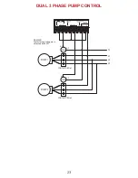
Page 21: ...21 TWO SINGLE PHASE PUMPS WITH A REMOTE INPUT LOW VOLTAGE DC SUPPLY REMOTE INPUT...

