36
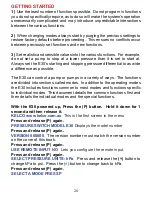
acceptable if the E30 is being used to directly drive a pump motor. If relay
1 is chosen as the output device and the intended application requires a
fast response, relay 1 with will impede the high-speed performance. For
such applications relay 2 should be used as its speed is only limited by the
speed at which its contacts can open and close. If you choose to use relay
1 then relay 2 will mirror relay 1’s action. It will be on when relay 1 is off
and it will be off when relay 1 is on. It can be used to control an external
alarm or simply in conjunction with relay 1 to provide a set of break before
make S.P.D.T. contacts. If you make relay 2 your chosen output device
then relay 1 will not be used. It will not respond to the state of relay 2, it will
simply remain open in all situations.
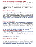
NORMALLY OPEN CONTACTS
After choosing which relay you want to use as the primary output device
the E30’s menu asks you how you want the chosen relay’s contacts to
behave. If you choose normally open, the contacts of the relay will remain
open until the system pressure reaches the set snap pressure, at which
point the contacts will change state and close.
NORMALLY CLOSED CONTACTS
If you choose to have the relay contacts normally closed then on boot up
the relay will close its contacts and they will remain closed until the system
pressure reaches the snap pressure, at which point they will open.
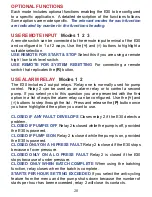
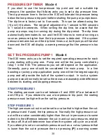
SET PRESSURE
Mode
3
The set or snap pressure is the pressure at which the switch will change
state from on to off or from off to on, depending on how you have con
fi
gured
the relay’s contacts. Enter your required set pressure in the range 7 to
2000 kPa or 1 to 290 psi. Press the
(P)
button to record your setting and
move to the next screen.
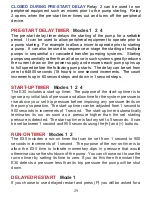
DELTA PRESSURE
Mode
3
Delta pressure is the differential pressure between the set on and off
pressures. The range of adjustment is 7 to 140 kPa or 1 to 20 psi in
increments of 7 kPa or 1 psi. The higher the value you enter the more
stable and tolerant the switch will become to minor pressure
fl
uctuations.
ALTERNATE THE PUMPS
Mode 4
Select NO if you want the 2 pumps to operate in a duty / standby
Summary of Contents for E30
Page 11: ...11 74mm 60mm 4 X 6mm Holes TOP WALL BRACKET DRILL PATTERN...
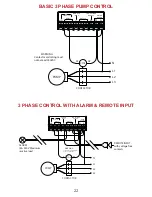
Page 19: ...19 WIRING DIAGRAMS PLUG PLAY CONNECTIONS CONNECTIONS FOR A SINGLE PHASE PUMP...
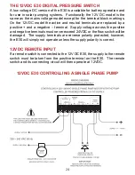
Page 20: ...20 LOW VOLTAGE AC SUPPLY WITH REMOTE INPUT CONNECT AN EXTERNAL ALARM...
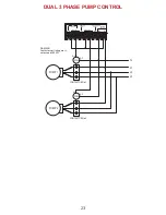
Page 21: ...21 TWO SINGLE PHASE PUMPS WITH A REMOTE INPUT LOW VOLTAGE DC SUPPLY REMOTE INPUT...

