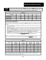
Multiplex Address
Switch B3
Switch B4
Switch B5
1
OFF
OFF
OFF
2
OFF
OFF
ON
3
OFF
ON
OFF
4
OFF
ON
ON
5
ON
OFF
OFF
6
ON
OFF
ON
7
ON
ON
OFF
8
ON
ON
ON
Mode
Switch A1
Switch A2
Switch B1
Switch B2
Set jumper plugs on
MUX Remote setpoint,
no local setpoint
ON
OFF
OFF
ON
NONE
MUX Remote setpoint,
4-20 mA local setpoint
ON
ON
OFF
ON
Positions 1 & 3
MUX Remote setpoint,
1-5V local setpoint
ON
ON
OFF
ON
Positions 1 & 4
MUX Remote setpoint,
Position 1
three-wire local setpoint
ON
ON
OFF
ON
(no jumper on 3-6)
MUX Remote setpoint,
two-wire local setpoint
ON
ON
OFF
ON
Positions 1 & 6N
22
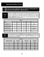
Select either a multiplexed remote setpoint with no local adjustment or a multiplexed remote set-
point with local adjustment and set DIP switches and jumpers per TABLE 16. If remote and local
setpoints are both enabled, the remote setpoint establishes the setpoint and the local setpoint has
±12.5% of the input adjustment around this point. If the local setpoint adjustment is by a PreCon
Two-Wire Potentiometer (as used in the “XA” option on PreCon Temperature Sensors) the local
setpoint adjustment is ±9.4% instead of ±12.5%.
STEP
D-1
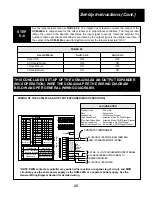
In the multiplexed PWM mode, each UCM-420A is assigned an address 1-8 so that it may be inde-
pendently updated by the Building Automation System. Multiple UCM-420As may be assigned the
same address. Assign each UCM-420A an address per TABLE 17. All UCM-420As with the same
address must have the same setpoint.
STEP
D-2
TABLE 16
TABLE 17
D
SET-UP OF THE UCM-420A AS AN OUTPUT EXPANDER WITH
MULTIPLEXED PWM INPUT (SEE PAGE 11)
Set-Up Instructions (Cont.)


