6 Assembly and first commissioning
6.1 Requirements for the installation site
The following requirements for the installation site must be met:
– The installation site must have an even and solid base.
– The installation site must meet the necessary static requirements, such as suf-
ficient load-bearing capacity for ceilings.
– the installation site must be in a room.
– The temperatures at the installation site should not fall below +5 °C and should
not 40 °C.
6.2 Requirements for power supply
The room air cleaner requires a 230 V 50/60 Hz safety socket. Connection to the
power supply may only be made using the power cable supplied.
WARNING
Fire hazard due to overload of multiple plugs, multiple
sockets or extension cables!
Overloading multiple sockets, multiple outlets or extension
cables can cause a fire. This can cause serious injury or death to
persons.
u
Make sure that any multiple plugs, multiple sockets and ex-
tension cables used comply with the applicable regulations
and that the characteristic values printed there are not ex-
ceeded by the connected devices.
Fluctuations on the voltage side max. +/- 10 %. Fluctuations on the frequency side
max. +/- 2 %.
To ensure a proper function may not be exceeded following values at the feed:
– Voltage interruptions up to 10 ms.
– Voltage drop to 1 term: Max. 20 % of the nominal voltage.
– Voltage peaks up to 1.5 ms with peak values up to 200 % of the nominal
voltage (RMS voltage) between outer cables.
6.3 Assembly and installation
Due to the stable construction, the room air cleaner has a weight of about 75 kg.
We therefore recommend that the installation, especially the lifting down from the
pallet, be carried out by several people..
1.) Ensure that the components cannot slip off the pallet after loosening the
clamping straps.
2.) Loosen transport protection such as foils and tension straps on the pallet.
3.) Lift the air cleaner from the pallet and place it on the four castors.
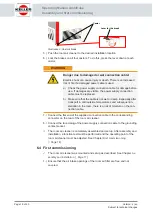
4.) Make sure that the brakes are released on all four castors. If necessary, re-
lease the brakes on each wheel. To do this, pull the lever on the castors up-
wards.
Operating Manual AmbiCube
Assembly and first commissioning
Page 17 of 40
Version: 2 | en
Subject to technical changes

