background image

25

Table of contents

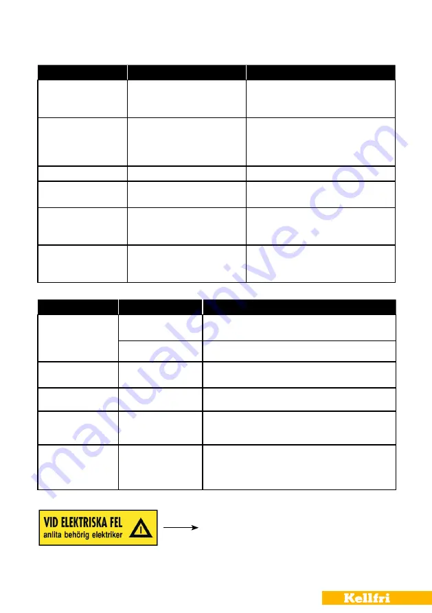
SERVICE

INTERVAL

MEASURE

Blades


Before each use

Replace all defective blades. Sharp blades give better results. 
When replacing blades, tighten bolts fully.

While operating

Listen out for noises

Infeed rollers

After 20 hours of 
operation

Lubrication

Hydraulics

Before each use

Search for leaks; check all connections and hoses

Safety fixtures

Before each use

Check safety devices.
E.g. safety valves, guards, etc. 

Bearing 

Regularly 
50 hours of operation

Lubricate bearings with grease regularly. If the machine is used a 
lot, all bearings should be greased every week. Otherwise, every 
50 hours of operation or once per year 

TROUBLESHOOTING

CAUSE

MEASURE

Poor chip quality, wood 
unevenly chipped

- Blunt blades.
- Cutting distance between blades is 
uneven or too wide.

- Check blades.
- Adjust and grind if required.

The chipper does not pull in 
the trees/branches

- The blades are facing the wrong way.
-  Blunt blades/Wrong angle on ground 

blades

- The feeder does not feed in the trees

- Check blades.
- Turn around, adjust and grind if required
-  Check that the feeder is correctly connected and 

is working properly.

Blockage in discharge chute - Operation speed too low.

- Increase speed to 540/1000 rpm.

Major vibrations

-  Cutting speed and infeed speed are 

not in synch.

- Adjust infeed speed.

Infeed rollers do not rotate 
or are too slow 

- No pressure in the hydraulic system.
- Low oil level in the hydraulic system.

-  Check the oil level and for any leaks in the 

hydraulic system.

- Fill with hydraulic oil.

Does not pull in all timber 
toward the chipper, rattles

- There is a piece of wood between the 
infeed rollers and the chipping disc.

-  Feed in a new log to press the remaining wood 

into the chipper or reverse the feed to remove 
the piece of wood.

TROUBLESHOOTING

NOTE Make sure the machine is turned off and disconnected before performing any intervention.

WARNING! In the event of an electrical fault, 
a qualified electrician must be consulted.

Summary of Contents for 13-WC17H2

Page 1: ...Read the operating instructions carefully before using the product Operating instructions translated from Swedish 13 WC17H2 CHIPPER...

Page 2: ...w control for infeed rollers 22 Safety check before machine maintenance 23 Clearing blockages 23 Maintaining feed rollers 24 Troubleshooting action 25 Setting chipping wood size 26 Extra cutting blade...

Page 3: ...maintenance Branch crusher for best results when chipping trees with branches On the cutting disc there are 4 blades with dou ble tempered cutting edges The chipper has an adjustable counter bar for d...

Page 4: ...dren must never be present within the work area never let children operate the machine The equipment functions optimally and most securely when it is used in the capacity for which it is intended do n...

Page 5: ...must be worn whilst the engine is running SURROUNDINGS Check that the work area is free from bystanders children and objects before hitching or us ing the equipment There is a risk of serious injury...

Page 6: ...re using it Read and understand all warning labels The most important safety aspect of the machine is that the user understands the machine and its instructions Z94207 Z94207 WARNING Do not step or pl...

Page 7: ...ned according to the figure below familiarise yourself with the decals and those that are essential for the safer use of the machine Think safety work safer NOTE Missing or torn warning decals must be...

Page 8: ...and tank powered via PTO Large pulley 180 mm Small pulley 120 mm Hydraulic oil tank 24 litres Length 400 mm Width 200 mm Height 300 mm Coupling 3 point Cat 1 2 Weight 560 kg Dimensions 2750 mm x 1630...

Page 9: ...sequently named in this operating manual Turnbuckle 3 point linkage 3 point linkage Attachment of PTO shaft Discharge chute Chute flap Discharge chute handle Hydraulic pump Flow control Upper chipping...

Page 10: ...lisers are folded down and standing on the ground during use Make sure that there are no foreign objects in the machine before it is used Check the PTO drive shaft and the 3 point linkage before conne...

Page 11: ...ith the tractor at low revs Then slowly increase the revs to the correct chipping speed 540 1000 rpm For best results a speed of 1000 rpm is recommended Leaves and pine needles can get stuck in the di...

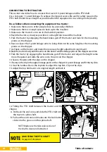
Page 12: ...a transport frame to protect it The discharge chute the control bar and the chute flap have to be fitted To fit these parts begin by removing the upper part of the protective frame with an angle grind...

Page 13: ...13 Table of contents 2 Install the locking device View from the inside of the infeed table 3 Install the control bar 2 pcs a 1 pc b Assembly on the right Assembly on the left a a b...

Page 14: ...Fit protective guard 4 pcs 5 Fit stabilisers 2 pcs 2 pcs Stabilisers are fitted on the right hand and left hand sides of the chipper IMPORTANT The stabilisers must be folded down and standing on the g...

Page 15: ...ress the green button and a red light will come on next to the electric valve When the emergency stop is used you must re start the chipper by pressing the green button Note This function must work ot...

Page 16: ...se points regularly Grease points must be lubricated every 20 hours Before repairing the hydraulic circuits make sure there is no pressure left in the system The cutting disc continues to rotate after...

Page 17: ...tor should review before using the equipment It is important to follow this list for personal safety and to maintain the equipment in good mechanical condition Before each time the equipment is used t...

Page 18: ...on the tractor and make the necessary height adjustments up down 8 Back the tractor slowly until the arms on the tractor and the linkage pins on the chipper are in line 9 Park the tractor by engaging...

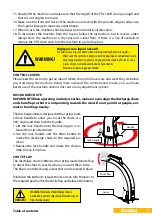
Page 19: ...it at people ani mals or buildings nearby Thedischargechuteisdesignedwithaspring load ed lock handle to allow you to set the chute at a 360 angle and then lock the handle 1 Lift the lock handle until...

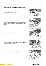
Page 20: ...t off the transmission shaft to the desired length NB The shaft may not be cut more than half the tube length 3 File the edges of the tube 4 Cut off the tube of the protective device to the same lengt...

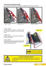
Page 21: ...bepulleduptomovethecontrolbarfrom the stop position 1 Mode Infeed 3 Mode Output NOTE Theresetbarhastobemovedto beabletochangethecontrolbar Reset bar Control bar 2 Mode Stop 1 Mode Infeed Push the rese...

Page 22: ...the material and conditions at hand The scale on the flow rate handle is numbered from 0 to 10 0 100 To adjust the flow 1 Loosen the thumb screw A 2 Move the handle to the required position B 3 Tighte...

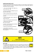
Page 23: ...d make sure the chipping disc turns freely SAFETY CHECK BEFORE MACHINE MAINTENANCE Disconnect the PTO shaft Turn off the tractor engine Make sure all parts in the machine have come to a standstill Rem...

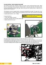
Page 24: ...nfeed rollers 4 Remove the four large wing nuts two on each side 5 Remove the springs used to tension the upper infeed roller 6 Remove the lower pin for the turnbuckle 7 Lift the upper infeed roller N...

Page 25: ...nches The blades are facing the wrong way Blunt blades Wrong angle on ground blades The feeder does not feed in the trees Check blades Turn around adjust and grind if required Check that the feeder is...

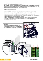
Page 26: ...with a 24 mm wrench A 2 Remove the cover by loosening the four bolts using a 13 mm wrench B 3 Remove the two bolts retaining the PTO shaft guard using a 16 mm wrench C 4 Swing back the upper chipping...

Page 27: ...is used NOTE All four blades must be mounted at the same time Cutting disc Extra spacers 4 pcs and adjustment spacer are included 1 Remove spacers from the cutting disc Fit the extra blade 2 Replace...

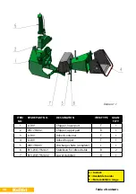
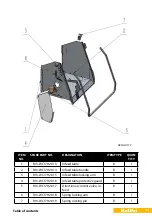
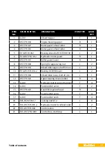
Page 28: ...part T 1 2 WC17H 002 Chipper upper part B 1 3 A DIV Infeed container T 1 4 A DIV Infeed hopper T 1 5 WC17H 003 Discharge chute complete L 1 6 R13 WC17H2 021 Stabilisers for infeed table B 2 7 R13 WC17...

Page 29: ...d table B 1 2 R13 WC17H2 014 Infeed table handle B 1 3 R13 WC17H2 015 Infeed table locking arm B 1 4 R13 WC17H2 016 Infeed table protective guard B 1 5 R13 WC17H2 017 Directional control valve in feed...

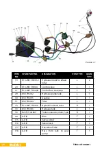
Page 30: ...box start stop L 1 29 WC17H 082 Hydraulic pump tank L 1 30 WC17H 095 Gearbox L 1 31 WC17H 084 Filter L 1 32 R13 WC17H2 010 Hydraulic oil tank cover B 1 33 WC17H 083 Hydraulic tank L 1 39 R23 TV100 08...

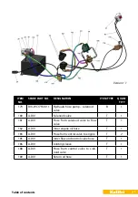
Page 31: ...DIV Solenoid valve T 1 181 A DIV Hose from solenoid valve to flow valve T 1 182 A DIV Inner engine oil hose T 1 183 A DIV Hose from control valve to engine T 2 185 A DIV Inner flow and control valve...

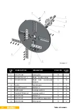
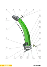
Page 32: ...2 Blade double cutting L 4 3 R13 WC15H 023 Blade bolt countersunk M10x45 L 16 4 A DIV Bolt M16x60 T 4 5 R35 HRT160 025 Washer 10 L 16 6 MTB50 002 Locking nut M10 L 16 7 R60 MUTTERL 021 Locking nut M1...

Page 33: ...anged bearing housing with bearing UC210 L 2 5 WC17H 045 Bolt M16x35 B 8 6 WC17H 048 Branch crusher L 1 7 WC17H 093 Belt pulley L 1 8 13 WC15HN 001 Speed control 1 9 WC17H 095 Gearbox L 1 10 WC17H 082...

Page 34: ...34 Table of contents Version 1 1...

Page 35: ...ring for upper wing nut L 2 9 WC17H 033 Infeed roller upper shaft 50 mm L 1 10 R13 WC15H 014 2 Bearing UCP208 lower L 2 11 WC17H 038 Infeed roller lower shaft 40 mm L 1 12 WC17H 026 Upper bearing slee...

Page 36: ...36 Table of contents Version 1 1...

Page 37: ...K251 024 M8 spring washer B 1 10 R27 EK251 036 Flat washer M6 B 22 11 WC17H 069 Bolt M6 x 25 B 7 12 R27 MD500 028 Screw M6x30 B 4 13 WC17H 071 Index bolt locking B 1 14 WC17H 072 Spring B 1 15 WC17H 0...

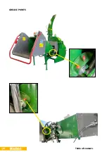
Page 38: ...38 Table of contents GREASE POINTS...

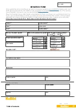
Page 39: ...on the type plate NB Do not forget to attach the pictures to the e mail when you send the form If the product was purchased from a dealer please contact the dealer in the first instance REASON YES 11...

Page 40: ...parts such as hoses seals oil and belts Kellfri AB Tel 46 511 242 50 E mail info kellfri co uk You are always welcome to give feedback or ask us about our equipment and products Kellfri AB has a poli...

Reviews: