background image

18

3

2

1

37

40

36

37

38

9

4

5

6

7

8

9

4

35

33

31

10
11

12

30

13

28
27

17

16

21

19

18

18

15 25

18

25

18

24

23

22

15

60

29

29

41 42 43 44 45

46 47 48

50

49

51

53

52

54

55

56 57

42

59

H

G

58

14

20

26

34

32

39

CUTTING HEAD

Summary of Contents for 27-HRT160

Page 1: ...Read this manual carefully before using the product Translated from the original 27 HRT160 HEDGE TRIMMER...

Page 2: ...th of the wire is 3 metres so that it will work on the frontloader or three point linkage The hedge trimmer s hydraulics are operated by a pump positioned on the tractor s power ta ke off Working spee...

Page 3: ...operator or others PRODUCT SAFETY INFORMATION Kellfris pasture topper is designed to operate efficiently at 540 rpm Make sure the PTO is set to 540 rpm The machine may only be used to cut hedges bush...

Page 4: ...ol indicates that a serious accident will occur if the instructions in the manual is not followed The accident resulting in serious injury possibly death or serious property damage This symbol indicat...

Page 5: ...he machine Risk of serious injuries can occur during operation Take an extra caution when children are in the area where the equipment product is being use or stored Check the area for low hanging ele...

Page 6: ...zone 15 m Warning ejection Keep distance Rotating Blades Warning leaking hydraulic fluid Prohibition to be on the machine Warning Risk of crushing behind the tractor when connect ing and disconnectin...

Page 7: ...ation correctly The product should not be taken into use unless it can be done in a safe way for the user Read the tractor s manual before connecting machine WORKSTATION The driver must remain in the...

Page 8: ...bolt in the protective device in the power take breaks and rotors still spinning while the PTO has stopped Operator s awareness is the key to safety around rotating parts Do not raise the machine whi...

Page 9: ...be visible and easily seen by the driver of the second vehicle Spectators must not lean on or climb on the machine during transport or during work NEVER allow anyone to ride on the machine The maximu...

Page 10: ...ion Make sure that the person driving the machine is aware of all safety measures and risks during op eration and when connecting and disconnecting the machine Do not connect the machine unto the trac...

Page 11: ...a tractor weighing approximately 1500 kg in order to be able to operate the crane in its outermost positions The mower can be used in different modes Sideways to cut the side of the hedge Lower posit...

Page 12: ...12 A1 A2 B1 B2 C1 C2 CM MIN MAX KGS L RPM CM CM CM KGS 160 25 40 1500 20 540 480 320 370 550 280 100 300 35 HTR160 TECHNICAL DATA...

Page 13: ...tions as recommended Use only spare parts with equivalent performance to reduce the risk of damage and failure Regularly check the condition of the machine Retighten bolts and other nuts as needed If...

Page 14: ...elivered partly assembled Use appropriate lifting instrument when lifting the machine from its packaging box make sure that the machine is steady and cannot tip over Remove all packaging material and...

Page 15: ...head to the lifting arm then tighten all bolts NOTE The head of the bolts should be mounted on the side where the cutouts are located shown with ar rows in the picture Then connect the hydraulic hoses...

Page 16: ...on nections if necessary Fill the oil tank with hydraulic oil approximately 20L Attach the machine to the tractor s three point hitch and connect the pump to the PTO Turn on the machine and run all cy...

Page 17: ...ge Cylinder 1 Beam R35 HRT160 081 Cylinder 2 Folding arm R35 HRT160 087 Cylinder 3 Bom cylinder R35 HRT160 075 Hydraulic motor Hydraulic tubes J K L LEVER FEATURES lifting arm up down folding arm up d...

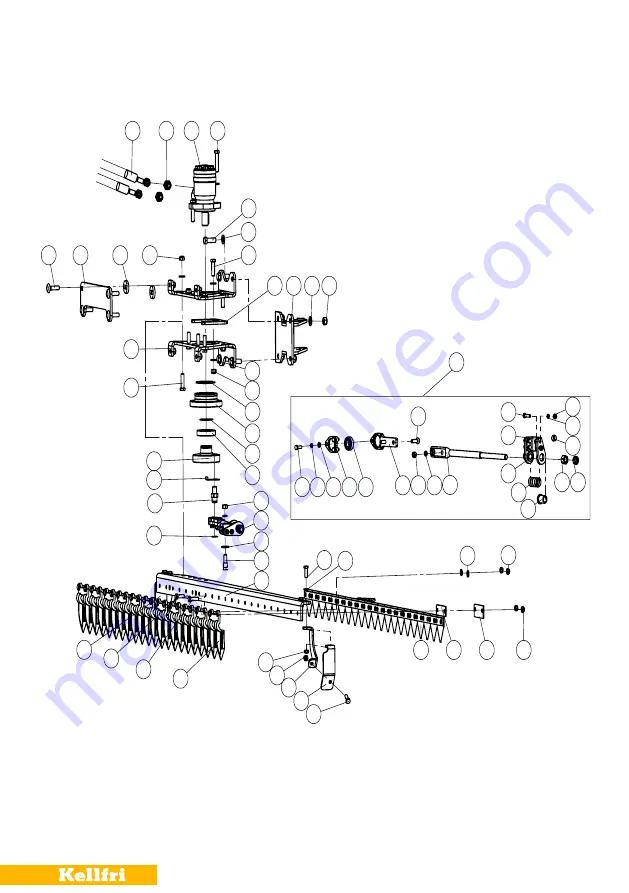
Page 18: ...37 40 36 37 38 9 4 5 6 7 8 9 4 35 33 31 10 11 12 30 13 28 27 17 16 21 19 18 18 15 25 18 25 18 24 23 22 15 60 29 29 41 42 43 44 45 46 47 48 50 49 51 53 52 54 55 56 57 42 59 H G 58 14 20 26 34 32 39 CUT...

Page 19: ...5 25 Washer10 28 26 Knife guard fixing plate 1 27 Hinge pin 1 28 Washer 16 8 29 Connecting rod combination 1 30 Nut M12 1 No Description Qty 31 Bearing 6009 1 32 Ring 45 1 33 Bearing seat 1 34 Ring 7...

Page 20: ...20 A B C D E F G H L J K K J L 1 2 3 4 5 7 8 9 6 14 10 15 21 16 17 18 12 13 41 39 1 3 37 36 21 21 26 30 29 33 34 40 23 22 17 18 11 28 35 24 24 25 27 26 31 31 38 20 19 BASE FRAME...

Page 21: ...n 12 3 16 Bolt M8x25 6 17 Washer 8 15 18 Nut M8 6 19 Valve supporting plate 1 20 Upper suspension shaft 1 21 Oil hose connector 4 22 Bolt M8x60 3 23 Quadruple remote control 1 24 Oil hose connector 4...

Page 22: ...0 3 7 Cylinder for small arm 1 8 Bolt M16x120 3 9 Bolt M16x100 2 10 Big arm 1 11 Bolt M20x130 2 12 Oil cup M6 4 13 Bolt M16x130 1 14 Cylinder for big arm 1 15 Double pipe clamp 4 No Description Qty 16...

Page 23: ...manual that comes with the machine Please fill in the details below and attach photo and other information in order to process your request Buyer Customer number Adress Invoice number E mail Phone nr...

Page 24: ...on of the machine inadequate service user inexperience or use of spare parts which are not original Wear parts such as hoses seals oils and mechanical belts According to 2006 42 EC Annex 2A Kellfri AB...

Reviews: