7
At this point, tighten the four bolts which
secure the arms on the cover. Next step, tighten
the bolts which keep the arms together. Then
tighten the bolts which hold the brackets.
(Illustration 4 or 5)
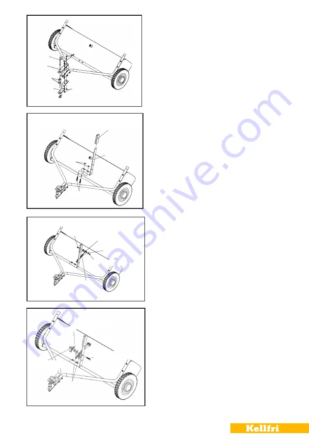
Fit the cotter pin, spacers
and locking pin on the tow bracket.
(Illustration 6)
Mount the height adjustment
lever on the collector’s axle as illustrated. Use
M8x40 bolts and lock nuts M8. Do not tighten yet.
(Illustration 7)
Put M8x20 bolt through the
angle bracket. Place on the bolt (in order): spacer
bushing, height adjustment bracket, a large
washer Ø8 and a lock nut. Tighten.
(Illustration 8)
Move height adjustment lever
to the side so that there is room for the washer
between lever and adjustment bracket. Tighten
the bolts which hold the adjustment lever.
5
Bolt M8x50
Locking pin
Attachment
Spacers
Flat bar
R-clip
Lock nut M8
6
Bolt M8x40
Handle
Height
adjustment lever
Lock nut M8
Bolt M8x20
Bushing
Washer M8
Lock nut M8
Height
adjustment bracket
7
Washer M8
Washer M8
Carriage bolt M8x30
Plastic knob
8
Summary of Contents for 35-GUB105
Page 14: ...14...


