


Kelly KLS-S Cheetah series Sinusoidal Permanent Motor Controller User
’s Manual
V1.13
9
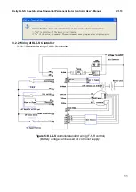
3.2 Connections
3.2.1 Pin definition of KLS-S Controller
Figure 4:
waterproof connector
1,The switch signal is valid to 12V on pin11
2,12V capacity is low.This 12V only can be used for LED or switch signals.
3,Boost and Brake analog regeneration mode used the same pin as pin2.
When Boost is disabled in the user program,the pin2 can be used as brake variable regen
mode.When Boost is enabled,the brake analog regen mode is inactivated automatically.Both
Boost and Brake variable regen mode can not be used at the same time.
DJ7091Y-2.3-11 Pin Definition
(14) REV_SW: Reverse switch input. Orange


