background image

Kelly KLS-S Cheetah series Sinusoidal Permanent Motor Controller User

’s Manual 


      V1.13 


16


Functional description: The max motor current is (The Value * Peak Current of the Controller). 
Suggestion: Factory default is 100%. 
 
(4)Battery Limit: Battery Limit Current, Limit the max value of Battery Current. Range: 20~100 
Functional description: Set max battery current so as to protect battery. A lower value means a 
lower battery output current and better protective effect. But excessively low value will affect 
acceleration. 
Suggestion: Factory default is 100%. 
 
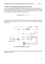
(5)Identification  Angle:  Please  download  the  instruction  to  how  to  use  Identification  angle 
function from the website. 
www.kellycontroller.com/support.php 
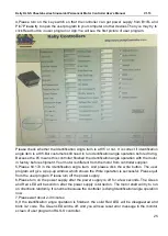
If you can read 85 in Identification Angle item, that is to say, the system is stable and normal. 
Please fill in 170 for Identification Angle item in user program. Then please click Write button in 
user program. Please wait a few seconds before restart the power supply. You will see some 
info on Monitor screen after power supply is 
reset.  If  you  see  Reset  error  on  the  Monitor  screen,  that  is  to  say,  the  auto_Identification  is 
finished. You can see 85 in the Identification Angle item again. And the controller will 
blink error code. This is normal. Please reset the power supply again. Then everything will be 
fine. The motor is ready to be drived by the KLS controller. 
Range: 85 or 170, nothing else. 
 
(6)TPS Low Err: Hall active pedal, if lower than the value, report the fault of TPS Type. Range: 
0~20 
 
(7)TPS High Err: Hall active pedal, if higher than the value, report the fault of TPS Type. Range: 
80~100 
As you may know, the output of hall throttle from Kelly is about from 0.86V to 4.2V. 
Our controller will report 3.3 error code if the output of hall throttle is below 0.5V or above 4.5V 
by default. 
The controller will think the hall throttle is shorted or damaged if the output is beyond the range 
from 0.5V to 4.5V. 
You can adjust the threshold voltage below or above 0.5V.The controller will report the 3.3 code 
to protect the system according to different types of hall throttle. 
Because there are many different hall throttle suppliers in the world. The initial output can not be 
always in the range of 0.5V to 4.5V. 
   
But it doesn't make any differences if you choose 0-5V or 3-wire pot for the throttle type. That is 
to say, hese two settings are only useful for hall active throttle or pedal when you chose throttle 
type at 2. 
   
As the same goes, it is valid to adjust the high threshold voltage above 4.5V or below 4.5V. 
Usually the hall output voltage is 4.2V Max. If you adjust it to lower value which is near 4.2V,it 
may trigger the error code in normal way. 

Summary of Contents for Cheetah Series

Page 1: ...Permanent Motor Controller User s Manual V1 13 Kelly Cheetah series KLS S Light flexible Sinusoidal Permanent Magnet Motor Controllers User s Manual Devices Supported Rev1 13 Jan 2023 KLS4812S KLS7212...

Page 2: ...r 3 Wiring and Installation 6 3 1 Mounting the Controller 6 3 2 Connections 9 3 3 Installation Check List 14 Chapter 4 Programmable Parameters 15 4 1 Step 1 15 4 2 Step 2 20 4 3 Step 3 21 4 4 How to u...

Page 3: ...efficiency requirements in the application of DC brushless motor It uses high power MOSFET s and SVPWM and FOC to achieve efficiencies of up to 99 in most cases A powerful microprocessor brings in co...

Page 4: ...5 switch inputs which are activated by connection to 12V Default to throttle switch brake switch reversing switch forward switch and Boost switch 11 3 analog 0 5V inputs that default to throttle inpu...

Page 5: ...luminum housing for maximum heat dissipation and harsh environment 15 Rugged high current terminals and rugged aviation connectors for small signal 16 Thermal protection current cut back warning and s...

Page 6: ...Operating Temperature Range 0 to 70 MOSFET temperature Operating Temperature Range 40 to 100 MOSFET temperature Max Battery Current Configurable 2 4 Name Regulation The name regulation of Kelly BLDC m...

Page 7: ...m water and contaminants To ensure full rated output power the controller should be fastened to a clean flat metal surface with four screws Applying silicon grease or some other thermal conductive mat...

Page 8: ...Kelly KLS S Cheetah series Sinusoidal Permanent Motor Controller User s Manual V1 13 7 Figure 2 KLS 18S mounting holes dimensions dimensions in millimeters...

Page 9: ...Kelly KLS S Cheetah series Sinusoidal Permanent Motor Controller User s Manual V1 13 8 Figure 3 KLS 30S mounting holes dimensions dimensions in millimeters...

Page 10: ...ow This 12V only can be used for LED or switch signals 3 Boost and Brake analog regeneration mode used the same pin as pin2 When Boost is disabled in the user program the pin2 can be used as brake var...

Page 11: ...1 Temp Motor temperature sensor input Raddle 5 5V 5V supply output 40mA Purple 18 Hall A Hall phase A Yellow 17 Hall B Hall phase B Dark Green 16 Hall C Hall phase C Dark Blue Notes 1 All RTN pins are...

Page 12: ...al Permanent Motor Controller User s Manual V1 13 11 3 2 2 Wiring of KLS S Controller 3 2 2 1 Standard wiring of KLS S controller Figure 5 KLS S controller standard wiring F N R control Battery voltag...

Page 13: ...ntroller standard wiring Three speed function control Battery voltage can be used for controller supply 3 2 2 2 Optional wiring of KLS S controller The 12V input signal of the pin supplies the second...

Page 14: ...S controller on pin11 Figure 9 Wiring diagram for motor temperature sensor 3 2 3 Communication Port A 4pin connector to RS232 port is provided to communicate with host computer for calibration and con...

Page 15: ...tor is still running let alone change the settings in the user program Make sure the wire is connected correctly Turn the PWR switch on The Green LED stay on steadily and Red LED turns off when the co...

Page 16: ...in7 to batteries for Identification Angle operation Please download the instruction how to use Identification angle function from our website www kellycontroller com support php 4 1 Step 1 1 Low Volt...

Page 17: ...e This is normal Please reset the power supply again Then everything will be fine The motor is ready to be drived by the KLS controller Range 85 or 170 nothing else 6 TPS Low Err Hall active pedal if...

Page 18: ...tle effective ending point Suggestion Set according to the practical situation factory default is 80 5V 4 0V 14 Max output Fre Max output frequency Unit Hz Functional description It will affect the to...

Page 19: ...actory default is Disable 21 NTL H Pedal Neutral position High Pedal Disable Only useful when Three gears switch function is enabled If enable the controller will detect the current pedal position or...

Page 20: ...tus Forward Switch Foot Switch FWD_SW 12 REV_SW 14 Foot 15 Enable Disable OFF OFF x Neutral OFF ON x Reverse ON OFF x Forward ON ON x Neutral Disable Enable x OFF OFF Can t operate x ON OFF Can t oper...

Page 21: ...expected after finish the Identification angle operation please just choose Change Direction item Please click Write button to activate Change Direction function The motor direction will be what you...

Page 22: ...rottle regen mode type The regen will happen as long as the throttle is released completely Factory set is 0 2 NTL Brk NTL Braking Percent the percent of Neutral Braking in max braking Range 0 50 Only...

Page 23: ...gram It will help the motor change the direction of motor quickly after you shift throttle from 0V to 5V or from 5V to 0V Suggestion factory default is Disable 11 Compensation Per Tried to increase th...

Page 24: ...or Android App Tablet or Cell Phone KLS S controller is designed for BLDC motor with three hall sensors By default the speed sensor type is set at 2 from factory setting for KLS S controller 1 Please...

Page 25: ...Tablet The third option is customers can buy our Bluetooth converter to connect the controller to Android Phone We don t have to use SM 4A to DB9 RS232 converter any more when you use Bluetooth conver...

Page 26: ...e shipment Your motor is different from the motor from controller supplier 5 Please fill 170 in the identification angle item And please click the write button The user program will give a pop up wind...

Page 27: ...picture of user program Please write 85 instead in identification angle by manual If there are no any error codes you can not write it back to 85 by manual Please wait longer time until the error code...

Page 28: ...connecting a load such as a contactor coil resistor or a horn across the controller s B and B terminals Remove any dirt or corrosion from the bus bar area The controller should be wiped with a moist...

Page 29: ...e will be regularly updated and published on the website Please Update your Configuration Software regularly You must uninstall the older version before updating Please try to use Identify function fo...

Page 30: ...pped but will restart when temperature falls below 80 2 4 Throttle error at power up Throttle signal is higher than the preset dead zone at Power On Fault clears when throttle is released 3 1 Reserved...

Page 31: ...or code is only valid for KLS 8080I controller Customers may read error codes in PC software or Android Tablet Contact Us Kelly Controls Inc Home Page http www KellyController com Download user manual...

Reviews: