


Kelly KLS-8080N/NPS Sinusoidal BLDC/PMSM Controller User’s Manual
V1.24.1
28
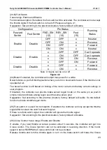
(11)
Compensation Per%
Tried to increase the current usage during Anti-Slip operation.
(12)IVT BRK MAX and IVT BRK MIN: These two items are only useful when Joystick function is
enabled in the user program. When you want to use Change Dir Brake to reduce the delay time
when you shift the direction under joystick operation, there is a RPM limitation to use Change
Dir Brake function which is only activated when the motor RPM is between IVT BRK MIN and
IVT BRK MAX.
Suggestion: factory default is Disable.
(13)Torque Speed Kp:3000
Torque Speed Ki:80
Speed Err Limit:1000
These parameters are used for PID adjustment. If the acceleration is too aggressive, please
reduce these three parameters at the same time,
vice versa. Please change the Torque Speed
Kp every 1000 units,
Torque speed Ki every 100 units and Speed Err limit every 500 units.
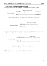
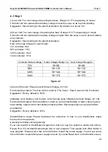
Note: Thermistor is optional. Default to KTY84-130/150 or KTY83-122
When controller temp item shows 246 in monitor screen of user program, it is normal. This
item is only useful for internal calculation for MCU.246 is about 11 degrees in environment.
4.4 How to use Identification angle operation for KLS-8080N controller
We must do Identification angle operation before running motor for all KLS controllers. The
Identification angle operation can be done in PC program or Android App(Tablet or Cell Phone).
KLS-8080N controller is designed for BLDC motor with three hall sensors. By default, the
speed sensor type is set at 2 from factory setting for KLS-8080N controller.
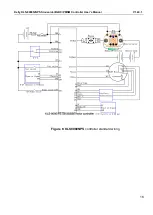
1,Please hook up the controller for identification angle operation according to the wiring
diagram below. Please make sure there is no load on the motor shaft before starting the
programming. The KLS-8080N is designed by opto-isolated technology. We specify 8-20V for
power supply pin7 vs pin6 which must be isolated from main battery pack B+/B-.Usually
customers can use 12V car battery or 12V Isolated type DCDC converter for this purpose.


