background image

14

SERVICE AND MAINTENANCE

1)  Tip the bowl into the downward position. Remove the shaft  

  endcap and carefully release the split pin.
2)  Drop the bowl out of the bearing assembly with the shaft still  

 attached.
3)  Re-position packing washers. To increase gear engagement  

  reduce the amount of washers at the top of the shaft and move  

  to the end of the shaft under the split pin. 
4)  Insert the shaft of the bowl back into the bearing arm   

 assembly.
5)  Insert more packing washers onto the shaft as required. There  

  should be no vertical movement or gap between the packing  

  washers and split pin.
6)  Insert split pin and using pliers bend split pin ends to secure.


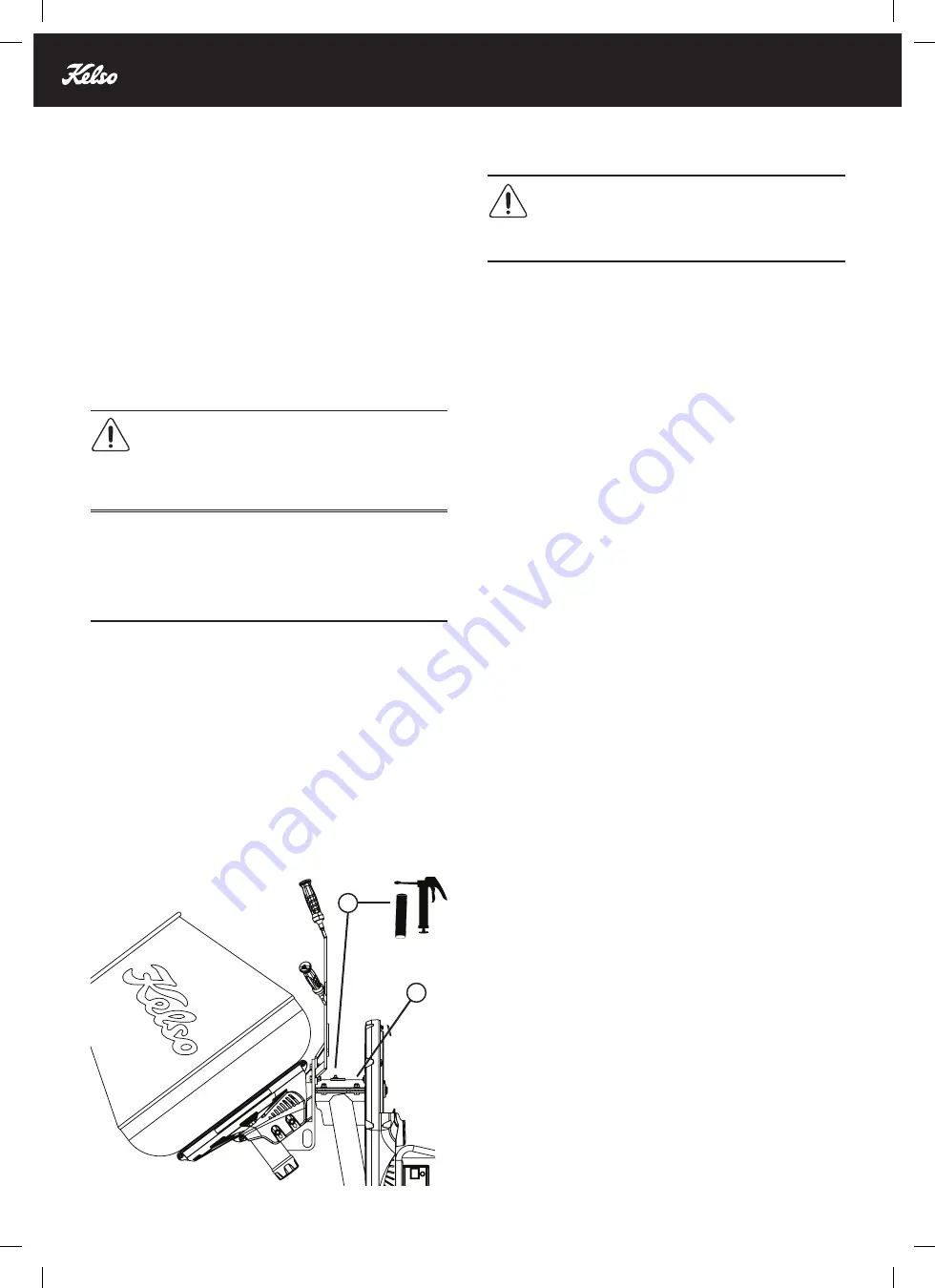
HOW TO APPLY GREASE TO THE TIPPING ARM


CAUTION!

 Do not mix grease types. Chemical incompatibility 

in lubricants can destroy bearings very quickly. It is advised to 

remove all old grease on the first service change to avoid risk.

NOTE:

 The grease nipple is a combination ball valve and check 

valve. The grease gun depresses the ball valve allowing grease 

to pass. When the gun is removed the valve should close, sealing 

in the grease. If the valve doesn’t close and grease leaks out, 

there may be particulate matter obstructing its proper operation. 

You should replace the nipple. 

•  Always clean off the grease nipple with a rag before 

attaching the grease gun coupler. This will prevent pumping 

contamination into the bearing assembly. 

(Figure 15 - A)

•  During first service, remove the top mount plate and clean 

away all old grease. 

(Figure 15 - B)

•  After cleaning, reattach the top mount plate and pump in new 

grease with a grease gun.

•  Periodically tip the drum using the tipping handles to help 

disperse the grease around the shaft. 

•  Pump enough grease that you hear escaping pressure and 

see just a little bit of grease movement squeeze out of the 

assembly.

•  DO NOT apply grease to the pinion gear or teeth ring. Grease 

can attract foreign contaminants leading to premature wear. 

CLEANING THE POWER TOOL


CAUTION! 

Do not point the water directly at any electrical 

components.

•  Clean the machine during and after every use. Remove any 

dust, residual mixing material and any other dirt. 

•  Cleaning is best done with a stiff brush. Wear safety glasses 

whilst brushing away dust and dirt.

•  Use running water from a hose or a high-pressure washer to 

clean the product.

•  After every mix it is advisable to clear any build-up of cement 

from the mixing paddles inside the mixing bowl. If left to 

dry the cement can be extremely difficult to remove without 

damage to the bowl. 


TIP: 

Run the Power Tool with a mixture of screenings and 

water to remove any dried or clogged cement from inside the 

mixing bowl.

•  After every mix it is advisable to clear any build-up of cement 

from the gears. If left to dry the cement can lead to premature 

wear.

•  After the last mix wash and clean ALL cement build up from 

both inside and outside the mixing bowl and any other exposed 

parts before the cement fully sets. 

•  Avoid hitting the bowl with any objects.
•  After cleaning the mixing bowl, the power tool should be stored 

with the mixing bowl in the downwards position to ensure all 

water is drained.

•  Remove grease and oil from the handle.
•  The ventilation holes on the motor cover must not be blocked.
•  NEVER use solvent-based cleaning agents, these may damage 

the painted surfaces or the plastic parts. If you must use these 

cleaning agents, test the effect of these agents on a small, 

concealed area

FIGURE 15

H

E

A

V

Y

 D

U

T

Y

G

R

E

A

S

E

A

B

Summary of Contents for KCM65

Page 1: ...fully and make sure that you understand the instructions before you use the product WARNING Work with concentration and care Keep your workplace clean and avoid hazardous situations This product could...

Page 2: ......

Page 3: ...1 INTRODUCTION CONTENTS TECHNICAL DATA 02 PRODUCT OVERVIEW 03 INTRODUCTION 04 SAFETY 05 OPERATION 08 SERVICE MAINTENANCE 10 SPARE PARTS LIST 14 TROUBLESHOOTING 15 WARRANTY 17...

Page 4: ...Rated Speed RPM 1400 1400 Bowl Speed RPM 30 30 Protection Rating IP44 IP44 Weight kg 85 110 Capacity Mixed Wet 65L 2 2CF 100L 3 5CF Capacity Unmixed Dry 85L 3CF 130L 4 5CF Gross Drum Volume 110L 4CF...

Page 5: ...er 3 Motor Cover 4 Motor Guard 5 Rear Grab Handle 6 On Off Switch 7 Adjustable Motor Mount 8 Wheels 9 Axle 10 L Frame 1 2 3 4 5 6 7 8 9 10 11 12 11 13 14 15 FIGURE 1 11 Lifting Points 12 Adjustable Le...

Page 6: ...sockets without ground cable Do only use extension cables with insufficient cross section A cross section that is too small may lead to excessive loss of power and overheating of the tool and the cab...

Page 7: ...ns and decals Do not use the power tool if it is defective Do not do modifications to this power tool Do not operate the power tool if it is possible that other persons have done modifications to the...

Page 8: ...ratory protective devices AS NZS 4501 Occupational protective clothing WORKING WITH WET CONCRETE DANGER Read the warning instructions that follow before you use the product CAN CAUSE SKIN BURNS EYE DA...

Page 9: ...mples of controls are dust collection systems and water sprays to bind dust Decrease dust at the source where possible Make sure that the equipment is correctly installed and used and that regular mai...

Page 10: ...otect the motor from overheating at extreme permanent load the power tool will be automatically switched off by the protective electronic system when a critical temperature is reached Run Time This is...

Page 11: ...re the power tool is turned off and the mixing bowl is stationary before reaching into or placing any objects into the bowl TRANSPORTATION WARNING Be careful during transportation The product is heavy...

Page 12: ...a to prevent access for children or persons that are not approved DISPOSAL DO NOT throw the power tool in your household waste Dispose of the machine accessories and packaging in an environmentally re...

Page 13: ...ic tyres and inflate to correct pressure as marked on the wheel X Examine the flexible power cable and the plug for signs of damage X Inspect all safety covers are secured and look for signs of damage...

Page 14: ...sed shop Electrical repairs are to be carried out only by qualified electricians at authorised service centres using original replacement parts If the power cord of this power tool is damaged it must...

Page 15: ...hold the motor to the motor mount Figure 11 A c Adjust the motor position forwards or backwards Figure 12 d Make sure that the V belt pulleys align and tighten the 4 bolts 8 Install the V belt inspec...

Page 16: ...handles to help disperse the grease around the shaft Pump enough grease that you hear escaping pressure and see just a little bit of grease movement squeeze out of the assembly DO NOT apply grease to...

Page 17: ...Rubber V Belt 40131332 40131349 8 KCM Safety Guard 2pce 40132155 40132162 9 KCM Pulley Cover Front Upper 40131073 40131073 10 KCM Motor Cover 40132193 40132193 11 KCM Bowls Shaft Cap 40130984 40130991...

Page 18: ...the mains power Motor is overheated This is normal temperature dependent overload protection has engaged Wait for the power tool to cool down Circuit breaker has been engaged Check circuit and switche...

Page 19: ...t Mixing bowl will not tip Bearing arm housing is over tightened Turn off power tool Loosen bolts and re check No lubrication Turn off power tool Check and apply grease via grease nipple Bearing arm h...

Page 20: ...the product was designed for as assessed by Ames 2 5 Failure or damage caused directly or indirectly by excessive use of the product within the 2 Year Limited Warranty period is excluded For the purp...

Page 21: ...ustralian Consumer Law For major failures with the service you are entitled to cancel your service contract with us and to a refund for the unused portion or to compensation for its reduced value You...

Reviews: