29
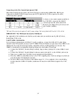
Connecting to the Edwards System Technology EST2
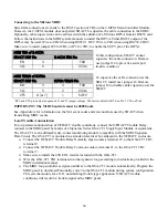
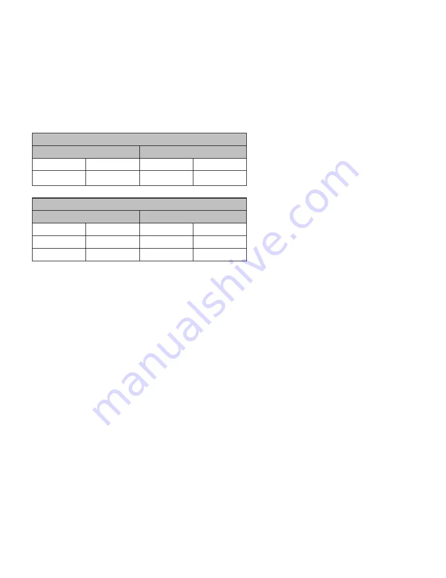
Serial data connections are made to the RS232 section of TB6 on the 2-MCM Main Controller Module.
However, the 2-MCM module does not permit SDACT to supervise the cable connection to the EST2.
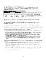
Optionally, cable supervision can be achieved with the addition of an Edwards IOP3A Isolator RS232
card. Follow the instructions in the EST2 system manuals to install the IOP3A. Either RS232 output of
the IOP3A may be used. Wire to TB2 when using RS232-1 OUT. Wire to TB3 when using RS232-2
OUT. Make sure to install jumper JP2 for TB2, or JP3 for TB3, to enable the SUPV pin of the IOP3A.
In this configuration, SDACT cannot
supervise the cable connection. Remove
user jumper J4 to prevent a serial port
trouble condition.
To supervise the cable connection at the
SDACT, install user jumper J4. Remove
jumper J4 to disable cable supervision at the
SDACT.
*
RTS and CTS pin numbers depend on J1 and J2 jumper settings. The factory default is RTS on Pin 7, CTS on Pin 8.
IMPORTANT: The EST2 baud rate must be 9600 baud.
See Appendix A for information on the SIA event codes and zone numbers used by SDACT when
transmitting EST2 events.
Local Trouble Annunciation
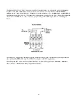
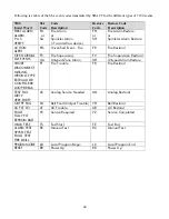
For on premises annunciation of S/FDACT trouble conditions, connect the S/FDACT Trouble Relay
contacts to the EST2 panel by means of a Signature Series SIGA-CT1 Single Input Module or equivalent.
The SIGA-CT1 is an addressable dry-contact monitoring module compatible with the EST2 Signature
Loop Controller. The SIGA-CT1 is mounted in a standard electrical box adjacent to the S/FDACT
enclosure.
Connect the S/FDACT Trouble Relay Normally Open contact, terminal 22, to the SIGA-CT1 TB2
terminal 8.
Connect the S/FDACT Trouble Relay Common contact, terminal 21, to the SIGA-CT1 TB2
terminal 7.
Make sure to install the 47K EOL resistor included with the SIGA-CT1.
Wire the SIGA-CT1 TB1 terminals into the signature loop according to instructions provided in
the EST2 installation manual.
The EST2 loop controller assigns an address to the SIGA-CT1 module automatically. Program the
EST2 panel to download Personality code 3 to the SIGA-CT1 module during system
configuration. This sets the module for a N.O. non-latching trouble type application. S/FDACT
trouble conditions will result in a trouble signal at the EST2 panel.
EST2 TB6 of 2-MCM
SDACT DB9 Pin
2-MCM TB6 Pin
RD 3 TXD
SG 5 COM
EST2 TB2/3 of IOP3A
SDACT DB9 Pin
IOP3A TB2/3 Pin
RD 3 3 TXD
SG 5 2 COM
CTS
8 (or 7)
*
1 SUPV

