background image

Kelvin Hughes


MANTA

DIGITAL

TM

 Quick Start Guide:  

Chapter 

5

Go to Run …


HBK-4002, issue 2 February 2013 

Page 

25

 of 

26


5.7  Stop transmission & antenna rotation 

Returning to the Standby screen from 

any 

navigation modes places the selected transmitter 

into standby thus stopping transmission and antenna rotation.  

This does not switch the transmitter OFF. 

Switching the 

MANTA

DIGITAL

TM

 display and/ or radar interswitch unit OFF does not isolate 

the power to transmitters, gearboxes or any associated sub systems.  


Warning: Working aloft


Placing the system in standby mode is not suitable protection for working aloft. 


When working aloft, all safety notices shown in the operator handbooks must be observed. 

This must include full isolation of all power to transceivers, gearboxes and any associated 

sub systems.


5.8  Switching OFF 

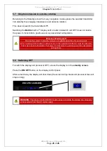
To switch the display and processor OFF, ensure the display is in the 

standby screen. 

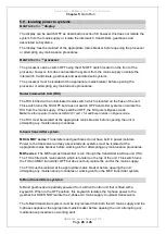
Press the 

ON/ OFF

 button on the display control panel.  

After a short delay the display will shut down (the screen will go blank and processor fans will 
stop running). 


WARNING

The display control ON/ OFF button does not isolate the display, the processor 

or transceivers from the AC mains supply.  


Summary of Contents for HBK-4002

Page 1: ...QUICK START GUIDE HBK 4002 Issue 2 February 2013 for V2 6 5 software SITUATIONAL AWARENESS THE WORLD OVER ...

Page 2: ...afety notices 3 3 Operator Handbooks 3 3 1 Handbook format 3 3 2 Export the handbook 4 4 Getting started 5 4 1 Switching ON 5 4 2 Standby screen overview 6 4 3 Single radar display overview 9 4 4 Display control panel 10 4 5 Trackerball and buttons explained 11 4 6 Virtual keyboard 12 4 7 Adjusting parameters on screen 13 4 8 MANTADIGITAL Control Interface MCI panel 15 4 9 Door locks and keys 16 5...

Page 3: ...liarise themselves with the full list of safety notices warnings and anti virus precautions that are contained in the MANTADIGITAL TM Operators handbooks HBK 4001 parts 1 and 2 3 Operator Handbooks 3 1 Handbook format Electronic copies of the system handbooks can be found on a CD supplied with the system This CD will be labeled HBK 5001 MANTADIGITALTM commercial handbooks These have been designed ...

Page 4: ...t From the Standby screen select Backup and Restore then click Export Operators Manual In a normal system the drives are allocated as follows C Main hard drive D Operating system E System Data F CD DVD ROM G Normally the USB flash drive If you are not in the correct drive click on the symbol to go up a level Select the memory stick and click Export The system will now download the handbooks to the...

Page 5: ...processor switch is in the OFF position the system cannot be started from the display Display ON To switch the system ON press the ON OFF button on the display control panel MantaDigital display control buttons Startup screen The system will now start and the two fans mounted in the MantaDigital navigation processor will run During the boot up start up sequence the following will appear on screen ...

Page 6: ... as Master selecting radar ECDIS or navigation and conning display modes will cause the selected transmitter to transmit and antenna to rotate Single Radar Display Sets the selected transmitter to run and starts Single Radar Display mode with a single PPI Dual Radar Display Sets the selected transmitter to run and starts Dual Radar Display mode with a primary and secondary PPI Conning Display Star...

Page 7: ...s connected to the system as Master or Slave The system is set to RUN by selecting any of the modes enabled in Go to Run see section 4 2 1 page 6 The current Software Version is displayed at the top of the standby screen as Software version ZM 2144 Vx x x where x x x is the version of software currently installed Selecting the software version automatically opens a new page that shows the software...

Page 8: ...r can be enabled at any time during the life of the equipment See the main operator s handbook HBK 4001 for additional details on optional features Set Up mode This area is password protected and is not available to the system user operator Backup Restore Allows the backup and restoration of data to and from a virus free USB memory stick Data includes system configuration routes user generated map...

Page 9: ...erview of the single radar Run screen layout Transmitter selection control Return to Standby Speed display selection Position display selection Spyscope wind depth optional CCTV Tracked target and AIS data Target AIS management Trails Vectors Route display and selection Screen control alarms change modes Heading display selection Orientation range heading line ownship chart settings Correlation Ga...

Page 10: ...l and display control buttons Repeated presses increases the illumination from OFF to maximum in 13 steps At the 14 th press the illumination returns back to OFF Screen brilliance Increases or decreases the main widescreen TFT display backlight illumination Press and hold the up and down buttons together for approximately 3 seconds to revert the backlight to the default brilliance level Switch scr...

Page 11: ...erball correspond to the on screen functions with each button action shown in the lower right hand side of the display If a button is blank no text then the button has no function In the Operator s handbook the button layout for each function is described as follows Left Middle Right AIS ON OFF AIS settings Safety Rel Msgs Switches AIS targets ON or OFF Opens the AIS settings dialog Opens AIS Safe...

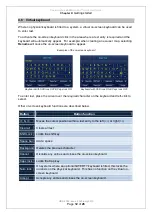
Page 12: ...Caps lock ON Keyboard with Shift lock ON Caps lock OFF To enter text place the cursor over the required character on the keyboard and left click to select Other on screen keyboard functions are described below Button Button function Moves the cursor position within a text entry to the left or right Clear all Clears all text Shift Lock Locks the shift key Space bar Add a space Backspace Deletes the...

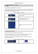
Page 13: ... or value Examples of sliders in a radar display Tune bar adjustment using the horizontal green slider bar Vector length adjustment using the horizontal green slider bar Adjustment of data view using a vertical slider 4 7 2 Adjusting numeric values Some functions required the adjustment of a numeric value This is achieved by placing cursor over the value to be adjusted Press and hold the left butt...

Page 14: ...or selection If the text is WHITE then the sensor is configured for use and is available for selection If the text is BLACK the sensor is configured for use but a signal is not being received This could be because the sensor is switched OFF or has a fault The sensor cannot be selected 4 7 5 Tabs Certain menus are accessed by selecting tabs These are selected by placing the cursor over the tab and ...

Page 15: ...ADIGITAL Control Interface MCI panel The optional MantaDigital Control Interface MCI panel allows the operator quick access to common functions including gain auto sea and rain clutter range EBL and VRM Each function is detailed in the relevant section of the operator s handbook i e for use of the Gain control on the MCI panel see Gain control in the operator s handbook HBK 4001 pt 1 A to Z operat...

Page 16: ... DVD drive USB port and the processor ON OFF switch on the MANTADIGITAL TM navigation processor USB socket Please refer to the main operator s handbook for information regarding anti virus precautions and warnings CD DVD drive access flap The access flap must be unlocked and opened to gain access to the CD DVD drive Processor power ON OFF Switches the processor ON OFF Note If the processor is swit...

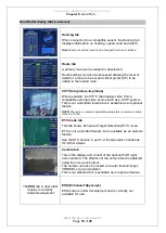
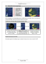
Page 17: ...G Antenna rotation Selecting Radar ECDIS or navigation conning display modes will cause the selected mastered transmitters to transmit and antennas to rotate 5 1 Single radar display Transceiver activation from standby screen When single radar display mode is started the transceiver selected as Master in the standby screen is set to Run causing it to transmit and the antenna to rotate Setting the ...

Page 18: ... the 2nd PPI The following functions can be adjusted independently of the primary PPI Screen orientation N UP C UP H UP True or relative motion Ownship screen offset Increase decrease range Control of trails Routes ON OFF ARPA AIS targets ON or OFF HL suppression Gain control ARPA AIS targets When acquired all radar tracked targets and AIS targets will be displayed on both the primary and secondar...

Page 19: ... as a CCTV system This is not a standard feature but is available as an optional feature NOTE There are no operator adjustable parameters or camera controls in the CCTV tab ETD mode tab This tab shows Enhanced Target Detection ETD mode ETD is not a standard feature but is available as an optional feature See the ETD section in part 1 of the Operator s handbook for further details Camera tab This i...

Page 20: ...lay Mode i e change mode without returning to Standby screen Conning display has no radar function so the transceiver is placed into Standby i e it does not transmit and the antenna does not rotate When changing to ECDIS or navigation conning display modes from Conning mode the transceiver will remain in standby Change navigation mode to Navigation conning display using Selected Display Mode i e c...

Page 21: ...ion mode controlling mastering a transceiver i e it is transmitting and the antenna is rotating Change navigation mode to Navigation conning mode using Selected Display Mode i e change mode without returning to Standby screen Navigation conning mode selected the transceiver continues to transmit and antenna rotates Stop the transceiver antenna Setting the system to Standby stops a mastered transce...

Page 22: ...ill rotate but radar interlay is not shown Transceiver activation when changing display modes A navigation mode controlling mastering a transceiver i e it is transmitting and the antenna is rotating Change navigation mode to ECDIS using Selected Display Mode i e not returning to Standby screen ECDIS selected the transceiver continues to transmit and antenna rotates Stop the transceiver antenna Set...

Page 23: ... to return to standby or change display modes using the Display Mode button Place the cursor over the Display Mode button which is located in the lower right hand side of the display The cursor tooltip will change to show the following options Left Middle Right Change Display Mode Show Sync status Capture Screen Opens Select Display Mode Opens the display network status indicator Takes a Jpeg scre...

Page 24: ...s shown at the top left side of the PPI In ECDIS systems that have the optional Radar interlay enabled select the Radar Control icon and place the cursor over the currently selected transceiver With the cursor over the transmitter control button the following options are available Standby screen Left Middle Right Select Radar Sensor Go to Standby Set H L skew Opens the radar sensor selection panel...

Page 25: ... systems Warning Working aloft Placing the system in standby mode is not suitable protection for working aloft When working aloft all safety notices shown in the operator handbooks must be observed This must include full isolation of all power to transceivers gearboxes and any associated sub systems 5 8 Switching OFF To switch the display and processor OFF ensure the display is in the standby scre...

Page 26: ...andbook HBK 4001 part 1 for additional details on Bypass mode The RIU must be isolated at the appropriate mains breaker before opening the unit or attempting any maintenance procedures X band transmitter system MK4 MK7 series Transmitters and gearboxes do not have built in power isolators Power to the transceiver and any associated sub systems must be isolated at the appropriate mains breaker befo...

Reviews: