X-band 12kW Upmast Magnetron Transceiver
Chapter 5: Mechanical installation
HBK-2300-3 Issue 2
Page 16 of 40
5.3
Antenna installation
CAUTION
Ensure that the antenna does not come into contact with the delicate protruding coaxial pin, this is a
critical component and should be treated with caution.
Follow all the instructions provided on the following page and ensure that the alignment guides are
used.
Before attaching the antenna to the pedestal unit, ensure that:
The pedestal base is securely fixed to the platform.
The power/ data cable is NOT attached.
The pedestal unit has a cap fitted over the open array mounting shaft to protect the
protruding co-axial pin. This cap must remain in place until you are ready to fit antenna to
the pedestal unit.
The pedestal power switch is in the OFF position.
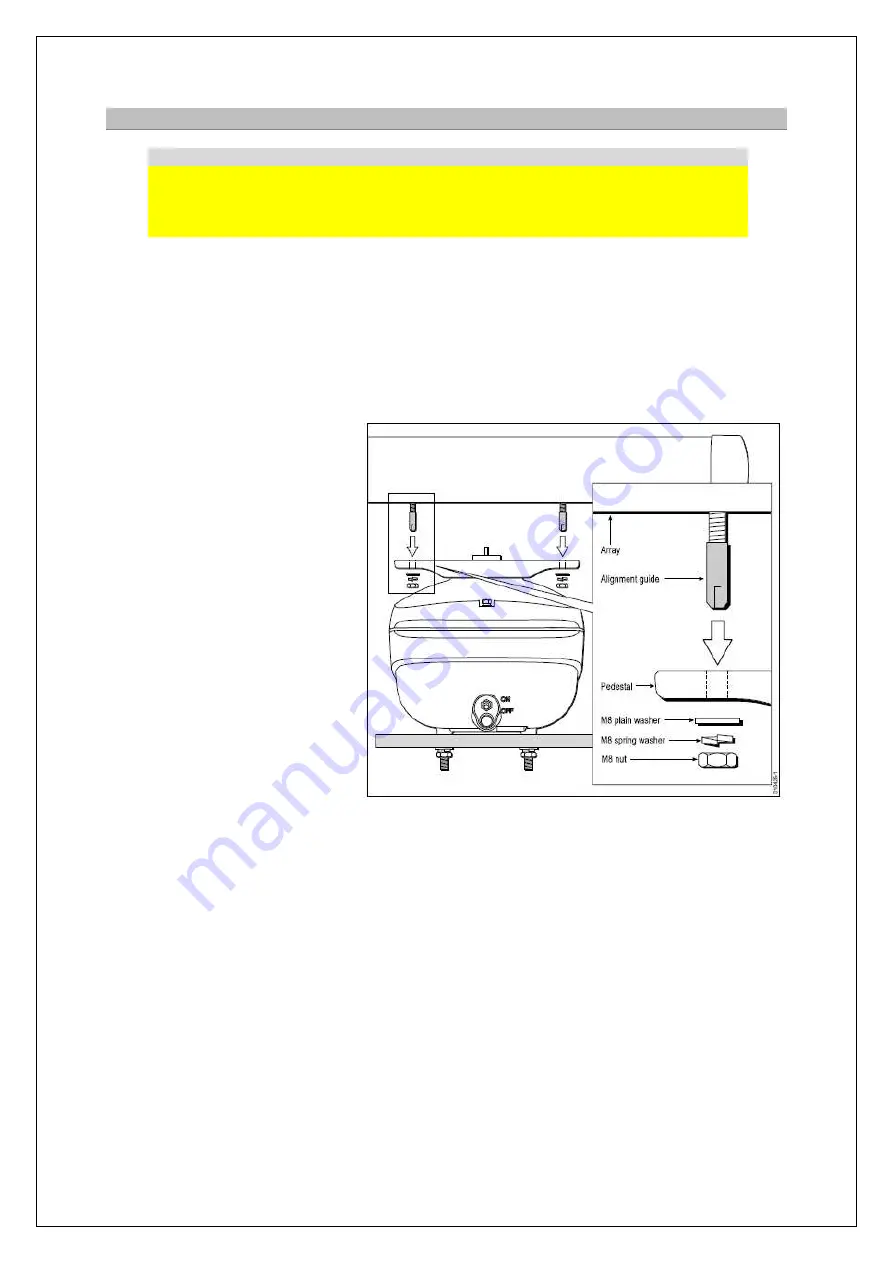
1. Fit the 4 threaded alignment
guides to the studs on the
underside of the antenna.
2. Ensure a close fit. The
alignment guides are essential
to help prevent damage to the
coaxial pin.
3. Remove the protective cap from
the antenna shaft. Retain the
cap for future use.
4. Position the antenna mounting
bracket on the Port to Starboard
axis of the pedestal.
5. Lift the antenna into position,
ensuring it is in the correct
orientation and that the threaded
alignment guides are fitted.
Carefully align and slowly lower
the antenna.
6. Once the antenna is in position, remove the alignment guides.
7. Grease the 4 securing studs with the supplied Denso paste.
8. Use the 4 nuts and associated washers to secure the antenna to the pedestal, as shown in the
following diagram.
9. Tighten each nut to 10 Nm torque.


