MOTOR & RELAY
Split phase motors are used in all compressors. Models
6-DF, 8-DF, and 10-DF have 2-pole, 3450 RPM motors.
The use of low starting torque motors is made possible
by unloading the compressor prior to the start, thus
reducing the required starting torque.
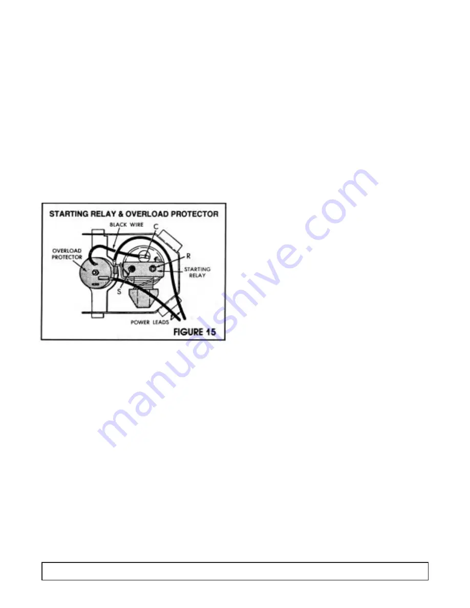
The starting relays on the “A” line compressors is the
push on type that mounts on the Start (S) and Run (R)
terminals of the compressor, as shown in Figure 15
below. The starting relay is a magnetic switch with start-
ing contacts. Its magnetic coil is in series with the run
winding of the motor. The relay coil carries the main
winding current. The relay armature holds the starting
winding contacts in open position except during the
starting period. At the moment of starting, when the
thermostat closes the electrical circuit, a surge of elec-
trical current passes through the main motor winding
and through the relay coil.
This energizes the relay coil and pulls up the relay arma-
ture, allowing the starting winding contacts to close. The
current through the start windings introduces a second
out of phase, magnetic field in the starter and starts the
value motor. As the motor speed increases, the main
winding current is reduced. At a predetermined condi-
tion, the main winding current, which is also the current
through the relay coil, drops to a value below that nec-
essary to hold in the relay armature. The armature drops
and opens the starting winding contacts and takes the
starting winding out of the circuit.
Refrigerant 404A compressors utilize a Positive
Temperature Coefficient resistor (P.T.C.) The PTC resis-
tor is connected in parallel with the run capacitor and in
series with the start winding. The PTC has a low resis-
tance when it is cold. When the motor starts the low
resistance causes a large current to flow through the
resistor. Current drawn by the resistor is out of phase
with the current drawn by the motor windings. As the
resistor draws current it begins to heat and resistance
builds to a point where it cannot flow to the start wind-
ings, thus switching current to the run windings.
In series with the motor windings is a separate bi-metal
overload protector held in place on the compressor by a
spring clip. The short wire lead on the overload protector
connects to the common (C) terminal on the compressor.
Should the current in the motor windings increase to a
dangerous point, the heat developed by passage of the
current through the bi-metal disc will cause it to deflect
and open the contacts. This act breaks the circuit to the
motor windings and stops the motor before any damage
can occur.
The overload protector provides added protection for the
compressor motor because in addition to protecting
against excessive current it also protects against exces-
sive temperature rises.
After an overload or a temperature rise has caused the
overload protector to break the circuit, the bimetal disc
cools and returns the contact to the closed position. The
time required for the overload switch to reset varies with
room temperature and compressor dome temperatures.
The overload protector is specifically designed with the
proper electrical characteristics for the compressor
motor and this ice cream cabinet application. Any
replacement must be made with the exact replacement
“NEVER SUBSTITUTE AN OVERLOAD
PROTECTOR WITH ANOTHER OF AN
UNAUTHORIZED PART NUMBER.”
The wrong protector can result in a burnt out motor. If
either the overload protector or the relay is found inop-
erative, both the relay and protector should be replaced.
When the thermostat cuts off after normal cycle or when
the service cord is pulled from the wall during a running
cycle, about eight (8) minutes time is required for
unloading (longer if it occurs during pull down), which is
the reduction of the pressure differential between the
high side and the low side of the system. During this
unloading period, the overload will trip if the service cord
is plugged into the electrical outlet.
If the compressor does not start, look for other trouble
(low line voltage—less than 100 volts at the compressor
terminals during the starting interval, inoperative relay,
inoperative compressor).
Since the relay is current operated and is designed for a
specific compressor and motor current value, the cur-
rent size relay represented by the part number is an
absolute must.
“NEVER SUBSTITUTE AN OVERLOAD
PROTECTOR WITH ANOTHER OF
AN UNAUTHORIZED PART NUMBER.”
These relays cannot be adjusted or properly repaired in
the field. If the compressor repeatedly starts and runs
for a few seconds, and then cycles on the overload pro-
tector, the starting relay contacts may be stuck closed
and the excessive current is tripping the overload.
16
GENERAL OPERATIONS


