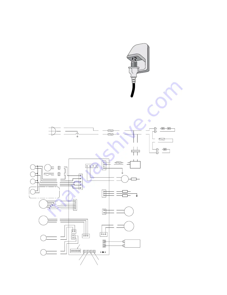
12 electrical connection
Kelvinator Gas Continuous Flow hot water system
Electrical connection
1. The water heater must be electrically grounded. Please
ensure that the earth on the outlet that the supply cord
connects to is wired correctly. If in doubt check the
continuity of the earth at the outlet to the earth stake on
the premises.
2. The water heater requires an AC 240V 50Hz
electrical power supply and draws a current of 0.8A.
3. The water heater must be connected to a weather-proof
power outlet. This outlet shall be no more than 1 meter
from the base of the water heater for easy access.
4. Means for disconnection must be incorporated in the
fixed wiring in accordance with the wiring rules.
5. The insulation of the fixed wiring must be protected by
insulating sleeving having an appropriate temperature rating.
6. If the supply cord is to be replaced, this must be done
by a service technician, electrician or similarly qualified
person in accordance with the wiring rules.
Weather-proof power outlet
Wiring diagram
IG
Elect rod
Heater
Thermostat
Heater
W
Y
B L
O
R
FM
Remote
Controller
2 3 4 5 6 7 8
1
Flow
Adjust
Valve
7
4
3
7
OFF
P
P
Inlet
thermistor
Mixing
thermistor
Burning LED
Propor-
tional
Valve
Flame rod
Ground
Air-fuel ratio rod
Flow
Sensor
3
9
5 3
7 3
MV
SV3
SV2
SV1
LB
G
O
R
O.H.C.F
Hi-
limit
BL
BL
BL
BL
BL
Only
Model 26
Model 24
BL
BL
PK
PK
C
1 8
1 7
1 0
+
4
6
5
6
+85-
R
W
BK
BK
BK
BK
BK
BK
R
R
W
Y
G
O
Trans-
former
BK
W
W
W
BK
BK
BK
W
BK
W
W
W
Ground
BK
W
Fuse
5A
MAIN PCB
GS00W-AU
イ
Increase button
Decrease button
MAX button
MIN button
Dip Switch
BK
W
AC240V
Ground
BR
BL
Y&G
BK
W
BK
W
Summary of Contents for KGC20BLA
Page 1: ...Gas Continuous Flow Hot Water System Installation Manual ...
Page 20: ...20 notes Kelvinator Gas Continuous Flow hot water system Notes ...
Page 21: ...Kelvinator Gas Continuous Flow hot water system notes 21 Notes ...
Page 22: ...22 notes Kelvinator Gas Continuous Flow hot water system Notes ...


