GENERAL OPERATIONS
PRINCIPLES OF OPERATION
13
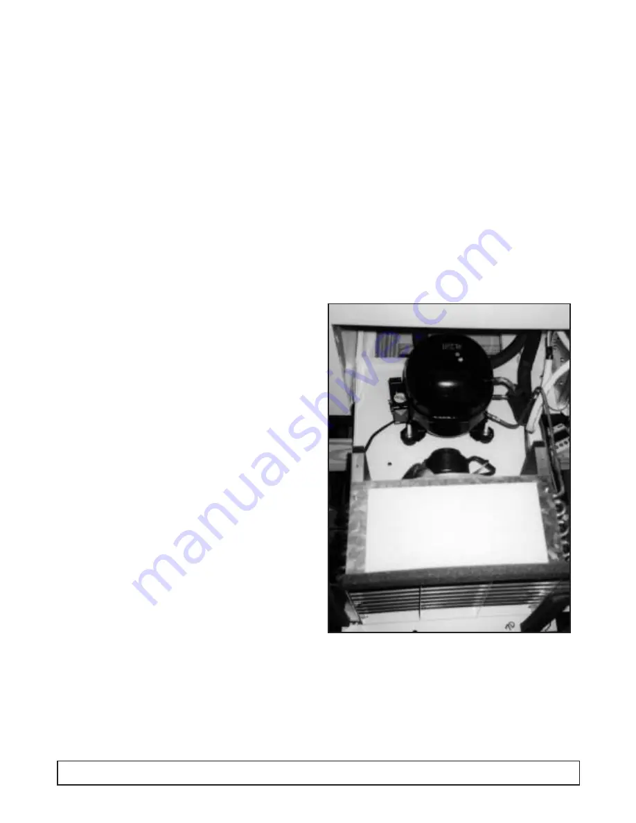
All the dipping cabinet models are of the same basic
design, consisting of a bare tube condenser and a cap
tube fed tank wrap evaporator.
Ice formation on the walls over a period of time is
normal. This frost should be scraped off periodically in
order to maintain peak performance. These cabinets
are thermostatically controlled for various temperature
requirements. The thermostat is located post adjacent
to the unit compartment and can be accessed for
adjustment by the user with a screwdriver or a dime.
Thermostat position #1 being the warmest and
position #7 the coldest.
These cabinets are manual defrost and a drain is
provided for periodic cleaning. A garden hose can be
attached to the drain plug for draining away any water
that might have accumulated. This drain attachment is
located in the front base rail of the cabinet. NOTE: The
power supply cord must be disconnected when
cleaning or servicing these cabinets.
NOTE: On initial cabinet pull down the bare tube
condenser may become warm to the touch until
the normal operating temperatures are achieved.
Refer to model serial data tag for cabinet amperage,
refrigerant charge & type.
Compressors being used in these cabinets utilize
refrigerant 404A and polyol ester oil. Because of the
hygroscopic nature of this oil, extreme care must be
taken when any component is changed within the
system. In the case of compressor replacement, work
should be completed before the caps are removed
from the compressor.
Agitation of the oil should be kept to a minimum.
Compressors should not be open to the atmosphere
for more than 15 minutes max. Should contamination
occur the oil can be removed and recharged (following
compressor manufacturer's guidelines when
performing this procedure). Because of the porous
nature of plastic, polyol ester oil should be stored in a
metal container. Moisture contained within the oil
cannot be removed even under high vacuum
conditions and must be replaced.
Dipping Cabinet 1298.02 2/3/03 1:14 PM Page 15
Summary of Contents for R-404A
Page 3: ...Introduction...
Page 13: ...SECTION II Principles of Operation...
Page 14: ......
Page 28: ......
Page 29: ...SECTION III Maintenance Repair...
Page 55: ...PARTS LISTING With Illustration Identification...
Page 56: ...CABINET PARTS EXPLODED VIEW 54 CABINET PARTS EXPLODED VIEW 2 1 3 4 7 9 8 6 10 11 5...
Page 60: ...CONDENSING UNIT EXPLODED VIEW 58 CONDENSING UNIT EXPLODED VIEW...
Page 62: ...ELECTRICAL PARTS EXPLODED VIEW 60 ELECTRICAL PARTS EXPLODED VIEW...
Page 64: ...1 6 7 2 4 3 5 LID EXPLODED VIEW 62 LID EXPLODED VIEW...
Page 66: ......
Page 67: ...ACCESSORIES...
Page 68: ......
Page 73: ...ADJUSTABLE LEG KIT 52 1831 01 ACCESSORIES 71...
Page 74: ...CASTER KIT 52 1830 01 72 ACCESSORIES...
Page 76: ...CAN CLAMP INSTALLATION 74 ACCESSORIES...
Page 79: ......
Page 80: ...by National Refrigeration Products 563 Corbin Road Honea Path South Carolina 800 486 8369...


