background image

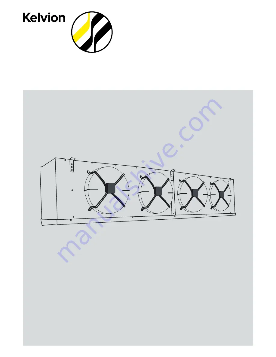
Searle Air Coolers

INSTALLATION AND 

MAINTENANCE 

INSTRUCTIONS

Summary of Contents for KEC10

Page 1: ...Searle Air Coolers INSTALLATION AND MAINTENANCE INSTRUCTIONS ...

Page 2: ...ccompany Searle manufactured Air Coolers The coolers are made up of heat exchanger commonly incorporating aluminium fin material and copper tube gal vanised steel casework and axial fansets These components will vary with application but the product function will remain common to remove energy from a working fluid generally as part of a refrigeration system This document is not a replacement for f...

Page 3: ...r is supplied on a frame with a unit but not a pipe to it the parts must be treated as separate components and data taken from individual nameplates Rotating blades dangling items of clothing jewellery or any items that could be pulled into the fan set are a hazard Keep safe working distance from the fan plate CAUTION All work on the units must be carried out by qualified personnel Installation an...

Page 4: ...nit leaking location of leak Items manufactured by Kelvion No work should be undertaken to resolve the problem either by the customer or a 3rd party until approved by Kelvion failure to do so could invalidate the warranty The item may be replaced or rectified if the guarantee claim is valid For items that have been installed Kelvion have the right to decide if rectification on site is suitable and...

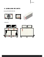
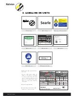
Page 5: ...5 3 LABELLING ON UNITS LabellingonKEC KME TEC DSR LSR SM 1 2 4 5 3 LabellingonFM 1 2 3 5 6 7 3 7 8 8 6 Labelling ...

Page 6: ... operating pressure suitable for this product 4 Fluid working group Reference to PED classification i e group 1 or group 2 2 If no safety device settings are detailed it is the installers responsibility to ensure an appropriately sized safety device is installed to prevent the product going over its maximum pressure rating Failure to do so may result in component product failure 3 Electrical suppl...

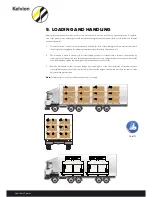
Page 7: ...lswhichcanbeidentifiedonKelvionpackingcartons Woodencrate GSLwoodencratesincorporateheattreatedtimberasappropriatealigningwithexportrequirements Careshouldbetakenwhenremovingunitsfrompackingtoensureunitisnotdamaged Keepdry Thiswayup Fragile Recycle Stacking 3 ...

Page 8: ... particularlyofthefinnedcoil 2 The drainpan is fitted to the unit in its transit lifting position for transportation Remove the draintray by removing the four fixings and then fit the hexagonal drain connection and gasket into the hexagonal well inside the draintray Handtightenthisassemblyusingtheknurlednutontheoutside 3 Refit the draintray in its transit position fixings loose making use of the s...

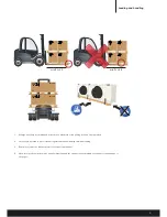
Page 9: ...ymarked 2 Careshouldbetakentoprotecttheunitagainstmechanicaldamagewhileunloading 3 Extreme caremustbetakentoprotectcoilconnectionsandfins 4 Upon receipt the units should be visually inspected and the supplier notified within seven days of any damage or shortages min PL 30 min PL 30 KEC 80 95 KEC 80 95 ...

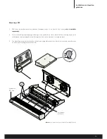
Page 10: ... hexagonal drain connection and gasket into the hexagonal well inside the draintray Hand tighten this assembly using the knurled nut on the outside When the cooler is in position ensure that the drainpan is dropped down into the operating position before tightening itsfixings FortheKMEunitswillhaveacabletiefixingthedraintrayalongthesideoftheunit 3 Placeintopositionusingthelocationguidance ...

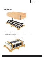
Page 11: ...cratepackaging plasticwrapping 2 On all DSR and LSR units the draintray is already fitted remove the four fixings securing the unit to the wooden pallet andplaceintopositionusingthelocationguidance Location guidance and installation ...

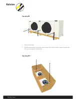
Page 12: ...er UnpackingSM 1 Removeplasticwrapping 2 On all SM units the draintray is already fitted remove the fixings metel brackets securing the unit to the wooden pallet Placeintopositionusingthelocationguidance UnpackingTEC ...

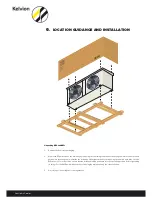
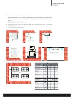
Page 13: ...directions 4 Maintenanceaccess shouldbeconsideredwhen locatingtheproduct includingadequatespaceforheaterwithdraw alwhenappropriate 5 Theunitisnotsubjectedtophysicalloads Models A B C D mm mm mm mm TEC all models 120 120 KEC all models 275 KME 50 60 350 KME 80 400 KME 95 450 KME 115 140 175 500 KME 232 282 650 KME 352 353 850 DSR all models 300 600 1200 LSR all models 1200 800 1200 SM 16 800 SM 20 ...

Page 14: ...erved before you hang the unit 2 Only fix the unit using the mounting slots provided refer to unit dimension drawings for slot measure ments Warning In case of improper installation leak of working fluid can occur during operation of the cooling equipment this can lead to injuries or damage to yourself or property ...

Page 15: ...g screws around three sides of the air off face offering up the verti cal drainpan and replacing the screws through the holes in the drainpan securing it in place 3 The blanking piece provided should be fitted in the original drain position If defrost is required on wall mount ed units refer to fitting instructions below Part Number WT Pan Part Number WT LT Kits Note Guard is supplied as part of t...

Page 16: ...applied wherenecessary Drynitrogenshouldbepassedthroughthepipeworkduringbrazingtominimiseoxidisation WARNING When brazing and leak testing are complete the suction line should be insulated with 3 4 thick Class O insulation The unit has been thoroughly tested during manufacture however after on site brazing is complete all pipework should be pressuretestedforleakstomaximum of1 3capacitypressure Bea...

Page 17: ...ine size is equivalent to that of the drain connection and that it has an adequatefall Condensatepumpkitoptions The condensate pump option is only available on high temperature units as a factory fitted item or can be bought as a spare ThePumpkitsaretotheDSRandLSRunits Pleaseseebelowfittinginstructionguides DSRCondensatepumpinstructions 1 Removetheendpanelofthecooler 2 Fit the sensor to the bracke...

Page 18: ... LSR SM FM It is important that the TEV is correctly sized and for maximum performance located within 100mm of the distributor inlet The TEV size should be determined using the maximum operational capacity and the minimum valve pressure drop This occurs at the minimum condensing pressure An externally equalised TEV must be used When calculating the minimum TEV pressure drop allowance must be made ...

Page 19: ...ngorreplacingthedistributorscrewedcap donotplaceexcessivestrainuponthedistrib utorleads If when the coil is operating at or close to its design temperature the TD is above normal that is to say the difference between the air entering the coil and the evaporating temperature is too great e g the evaporating temperature is low check the TEV superheat If it is above 0 9 TD and will not respond to adj...

Page 20: ...by this ratio and the resultant is the diameter of the orifice required If the larger of the two orifices is oversize drill out the smaller orifice to suit Always drill undersize then recheck the pressure drop to determine whether further enlargement is necessary If the pressure drop is within upper limits of the curve solid portion but the TEV is unstable the orifice must be furtherenlargedtobrin...

Page 21: ...n 12 EVACUATION Fluid coolers using water or water based solutions must be protected by adding anti freeze in sufficient concentration as it isnotpossibletodrainthesystemcompletely Note Theheattransferpropertiesofafluidvarywiththeconcentrationofadditives Evacuatethesysteminaccordancewithstandardrefrigerationoperatingprocedures codesandregulations ...

Page 22: ...rs won t change the rotation In optional AC fan Contactor boxes the fan contactors are energised through these auto reset normally closed thermo stats When internal thermostats are not used three phase motors MUST be protected against overload and single phasing Overloads must be set to cut out at FLC 10 FLC 15 at 30 C Failure to comply will render motorwarrantiesvoid Kelvion would recommend as ge...

Page 23: ...eed ConnectSupplyTo TerminalBlockTerminals1andN 4 Lowspeed Linkterminalblock terminals1 2 5 Defrostheaters Ifrequired TerminalBox 218 901 013 271 111 145 KEC10 15 20 25 30 FAN DEFROST Note 1 Supply230V 1Ph 50Hz 2 AppliesToKECRange 3 SingleFanOnly KEC10 Special KEC15 Special KEC20 Special KEC25 Special KEC30 Standard KEC10 Standard 4 DefrostHeaters IfRequired 5 TerminalBox 218 901 013 271 111 146 ...

Page 24: ...ock Terminals1 2 5 Defrostheaters ifrequired 6 TerminalBox 218 901 015 271 111 147 KEC35 40 45 55 70 FanandDF Note 1 FansSupply230V 1Ph 50Hz 2 DefrostHeatersSupplyOption 3 230V 1Ph 50Hzor400V 3Ph 50Hz 4 RemoveLinksBefore Con necting 3PhSupply 5 AppliesToKECRangeOnly KEC35 Special KEC40 Standard KEC45 Standard KEC55 Standard KEC70 Standard 6 DefrostHeaters IfRequired 7 TerminalBox 218 901 014 271 1...

Page 25: ...t Ref Drg 271 111 125 4 TerminalBox S 290 660 W 290 661 W KME50 175 1PHASEFANSUPPLY Note 1 FanSupply230V 1Ph 50Hz 2 AppliesToKMeRangeOnly KME50 601Fan KME80 952Fans KME115 1403Fans KME1754Fans 3 ForHeaterArrangement KME50 95 Ref Drg 271 111 171 KME115 175 Ref Drg 271 111 172 4 TerminalBox S 190 631 W 2F 190 632 W 3F 290 633 W 4F 290 641 W 1F 271 111 171 271 111 124 ...

Page 26: ...111 125 4 TerminalBox S 290 660 W 290 661 W KMe50 175 3PHASEFANSUPPLY Note 1 FanSupply400V 3Ph 50Hz 2 AppliesToKMERangeOnly KME50 601Fan KME80 952Fans KME115 1403Fans KME1754Fans 3 ForHeaterArrangement KME50 95 Ref Drg 271 111 171 KME115 175 Ref Drg 271 111 172 4 TerminalBox S 290 634 W 2F 290 635 W 3F 290 636 W 4F 290 642 W 1F 271 111 172 271 111 125 ...

Page 27: ...RangeOnly TEC1 3 51Fan TEC4 52Fans TEC7 83Fans 3 ForHeaterArrangement Ref Drg 271 111 451 4 TerminalBox S 44 10 602 W 110 621 W TECDEFROSTHEATERS Note 1 Supply230V 1Ph 50Hz 2 AppliesToTECRangeOnly 3 ForFanArrangement Ref Drg 271 111 450 4 TerminalBox S 218 143 110 271 111 450 271 111 451 TrayHeaters Wallmountoption ...

Page 28: ...TerminalBlockTerminals2AndN 4 LowSpeed LinkTerminalBlock Terminals1 2 5 HeaterOption RemoveLinkBefore Connecting2ndPhaseSupply 6 TerminalBox 210 608 W DSR36to83 FANSUPPLY Note 1 Supply230V 1Ph 50Hz 2 AppliestoDSRRangeOnly DSR36 42 2fan DSR51 62 3fan DSR68 83 4fan 62 3fan 3 Highspeed Connectsupplyto terminalblockterminals2andN 4 Lowspeed Linkterminal blockterminals1and2 5 Forheaterarrangement ref D...

Page 29: ...271 113 401 5 TerminalBox 210 609 W 271 113 403 DSR100 116 FANSUPPLY Note 1 Supply230V 1Ph 50Hz 2 AppliesToDSRRangeOnly DSR100 DSR116 3 ForHeaterArrangement Ref DRG 271 113 404 4 TerminalBox 210 607 W DSR100 116 DEFROSTHEATERS Note 1 DefrostHeaterSupply400V 3Ph 50Hz 2 AppliesToDSRRangeOnly DSR100 DSR116 3 ForFanArrangement Ref Drg 271 113 402 4 TerminalBox 210 610 W 271 113 402 271 113 404 ...

Page 30: ...ly400v 3ph 50hz 2 AppliestoSMrange3 4fanonly 3 Commonfanjunctionbox 4 Forheaterarrangement REF DRG 271 112 215or REF DRG 271 112 215 LV Asapplicable 5 Terminalbox s 290 635 w 3F 290 636 W 4F SM16to30 DEFROSTSUPPLY Note 1 Defrostheatersupply 400v 3ph 50Hz 2 AppliestoSMrangeonly 3 Forclaritymultipledefrost Heatersnotshown 4 Forfanarrangementref Drg 271 110 101 5 Terminalbox s 23 000 623 L1 L2 23 000...

Page 31: ...e 1 Fansupply400v 3ph 50hz 2 AppliestoFMrangeonly 3 Commonfanjunctionbox 4 Forheaterarrangement REF DRG 271 112 215or REF DRG 271 112 215 LV Asapplicable 5 xTerminalbox 218 143 202 FM SMPeripheralheater Note 1 Supply230v 1ph 50hz 2 AppliestoFM SMrangeonly 3 Forfanarrangement REF DRG 271 112 213or REF DRG 271 112 215 LVor REF DRG 271 112 215 4 TerminalBox S 218 143 101 5 OptionDualPhasePeripheral 6...

Page 32: ... Terminalbox s 21 000 623 L1 L2 23 000 624 L3 6 Forperipheralheater Arrangement ref Drg 271 112 214 FM20to36 DEFROSTDELTA 1 Note 2 Defrostheatersupply400v 3ph 50Hz 3 AppliestoFMrangeonly 4 Forclaritymultipledefrostheaters notshown 5 Forfanarrangementref Drg 271 112 210And271 112 211 6 Terminalbox s 21 000 623 L1 L2 23 000 624 L3 7 Forperipheralheater Arrangementref Drg 271 112 214 271 112 212 271 ...

Page 33: ...ngeonly 3 ForclaritymultipledefrostHeatersnotshown 4 Forfanarrangementref Drg271 115 173 F 5 Terminalbox 290 668 wor431 010 124 LSR12n FANSUPPLY Note 1 Fansupply400v 3ph 50hz 2 AppliestoLSRrangeonly 3 Commonfanjunctionbox 4 Forheaterarrangement Ref Drg 271 115 173 E 5 Terminalbox 290 636 w 271 115 173 E 271 115 173 F ...

Page 34: ...omparisontoahotgassystem HG E C HG E D Where there are two or more evaporators on a refrigeration system it is possible to defrost one using the hot gas generated in theoperatingof the other Thisarrangement allowsdefrostflowtobe inthesamedirectionascoolingflow Although this arrangementcanoperateonatwoevaporatorsystemthequantityoflowpressure superheatedgasisminimal therefore it is recommended that ...

Page 35: ...etensioning To avoid damage to either the coil fins or the heater cable theheatercableshouldbeinsertedintoasimilarlengthof1 4 ODcoppertubeandfedcarefullythroughthefinswithatwist ingmotion Withcaretheheaterelementsheathscanbecurvedthrough90 minimumradius600mm forremovalandrefit tingpurposes Beforeattemptingtorefitaheateritisessentialtoensurethatthecoilheaterholehasnotbecomeobstructed withiceandwher...

Page 36: ...guards and general casework Care must be taken when cleaning the fins to prevent damage A soft brush andmilddetergentsolutionisrecommended Thefollowingroutineannualmaintenanceisrecommended Checksecurityoffixingsespeciallyfanmotormountings Checkrefrigerantpipelinefordamageandleaks Checkallmotorsrotatefreely Checkelectricalconnectionsforsecurityofattachment Checkheatexchangercoilforbuild upofdebriso...

Page 37: ...ve 2006 42 ECMachinesDirective En378 Parts1to4 Refrigerationsystemsandheatpumps technicalsafetyandenvironmentalrequirements 2006 95 ECLowVoltageDirective EN60204 1 1999Safetyofmachinery Electricalequipmentofmachines BSEN61032 1998Protectionofpersonsandequipmentbyenclosures Probesforverification propellerfanunits BS EN13857 2008 Safety of machinery Safety distances to prevent hazard zones being rea...

Page 38: ...TEC4 TEC5 TEC6 TEC7 TEC8 Ceiling Mounting T2 LTKIT T3 LTKIT T3 5 4 T5 6LTKIT T7 8LTKIT Wall Mounting WT1 2LTKIT WT3 LTKIT WT3 5 4 WT5 LTKIT WT6 LTKIT WT7 8 Wall mounting kits WT1 2 PAN WT3 PAN WT3 5 4 PAN WT5 PAN WT6 PAN WT7 PAN WT8 PAN Model No of fans A Defrost Coil kW Tray kW TEC1 1 453 x4 275 2 x 250 TEC2 1 453 x4 550 2 x 250 TEC3 1 618 x4 700 2 x 325 TEC3 5 1 793 x4 900 2 x 425 TEC4 2 793 x4 ...

Page 39: ...work 133 133 1 D Conn 427 5 427 5 48 855 Drain pan F KEC35 45 Heater removal 600mm either end 1326 O A length 1300 Casework 133 133 1 D Conn 377 5 377 5 48 1305 Drain pan 653 653 550 F Heater removal 600mm either end KEC55 70 1826 O A length 1800 Casework 133 133 1 D Conn 48 1805 Drain pan 427 5 427 5 475 475 F Hanging bracket for KEC Models Coil conns end 489 MTG CTRS R6 5 25 30 15 17 5 46 524 O ...

Page 40: ...l drain pan 1180 5 Heater removal 53 2732 1220 Mounting CTRS 600 146 146 265 466 600 466 2736 Overall drain pan 1366 600 1220 Mounting CTRS F KMedrawingsanddimensions KME 175 KME 232 282 146 2065 Mounting CTRS 146 2357 2361 50 Heater removal F F Note All dimensions in mm F Min heat Withdrawal Model A F KM 50 350 805 KM 60 350 1200 KM 80 400 1200 KM 95 450 1200 KM 115 500 1200 KM 140 500 1200 KME 3...

Page 41: ... 1295 5 Required space LSR121 44 LSR121 64 LSR122 44 LSR122 64 LSR123 44 LSR123 64 LSR124 44 LSR124 64 LSR121 46 LSR121 66 LSR122 46 LSR122 66 LSR123 46 LSR123 66 LSR124 46 LSR124 66 117 130 180 200 237 266 301 341 114 125 175 192 230 256 292 326 151 180 232 277 314 382 405 496 141 165 216 254 291 348 374 446 Model Cu Al weight kg Cu Cu weight kg LSRdrawingsanddimensions LSR 123 Coil conns end 243...

Page 42: ... 1425 MNTG CRS 16mm MTG hole 150 412 A B MNTG CRS 1425 Power supply input Rfrig connections Heater removal 2000 Min 2 BSP M Drain conn 4425 740 1425 MNTG CRS 16mm MTG hole 150 412 A B MNTG CRS 1275 Power supply input Rfrig connections MNTG CRS 1425 Heater removal 2000 Min 2 BSP M Drain conn 5700 740 1425 MNTG CRS 16mm MTG hole 150 412 A B MNTG CRS 1275 Power supply input Rfrig connections MNTG CRS...

Page 43: ...50 412 A B MNTG CRS 1275 Power supply input Rfrig connections MNTG CRS 1425 Heater removal 2000 Min 3150 1220 150 412 A B MNTG CRS 1425 Power supply input Rfrig connections MNTG CRS 1425 16mm MTG hole 2 BSP M Drain conn 1575 1220 150 412 A B MNTG CRS 16mm MTG hole 1875 Heater removal 1000 Min 2 BSP M Drain conn Model Dim A Dim B FM20 1016 1468 FM24 1219 1671 FM30 1524 1976 FM36 1829 2281 Dim C 595...

Page 44: ...ase MTG hole 1315 MTG CTRS Refrig connection Refrig connection 1315 Base MTD CTRS Heater removal 2000 min 21 Mounting hole A 4325 1315 MTG CTRS 210 2 BSP M drain conn 1315 Base MTD CTRS 15mm base MTG hole 1315 MTG CTRS Refrig connection 1315 Base MTD CTRS 1315 Base MTD CTRS 1315 MTG CTRS Heater removal 2000 min 21 Mounting hole A 5600 1315 MTG CTRS 210 2 BSP M drain conn 1275 Base MTD CTRS 15mm ba...

Page 45: ...02 8x 163 4x 163 6x 163 8x 203 4x 203 6x 203 8x 243 4x 243 6x 243 8x 303 4x 303 6x 303 8x 244 4x 244 6x 244 8x 304 4x 304 6x 304 8x 16 20 16 20 24 30 16 20 24 30 24 30 1 1 2 2 2 2 3 3 3 3 4 4 4 6 8 4 6 8 4 6 8 4 6 8 4 6 8 4 6 8 4 6 8 4 6 8 4 6 8 4 6 8 4 6 8 4 6 8 970 1173 970 1173 1376 1681 992 1195 1398 1703 1398 1703 1141 1344 1141 1344 1547 1852 1141 1344 1547 1852 1547 1852 218 248 251 258 296...

Page 46: ...Searle cooler Installation and maintenance April 2016 272 000 296 www kelvion com ...

Reviews: