31
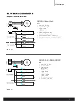
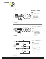
Wiring diagrams
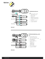
SM 16 to 30 (3 & 4 FAN SUPPLY)
Note:
1.
Fan supply 400v - 3ph - 50hz.
2. Applies to SM range 3&4 fan only.
3. Common fan junction box.
4.
For heater arrangement:
•
REF. DRG. 271-112-215 or/
•
REF. DRG. 271-112-215.LV
(As applicable).
5. Terminal box(s): 290-635-w(3F);
290-636-W(4F)
SM 16 to 30 (DEFROST SUPPLY)
Note:
1.
Defrost heater supply
400v - 3ph -50Hz.
2. Applies to SM range only:
3. For clarity multiple defrost
Heaters not shown.
4.
For fan arrangement ref. Drg
271-110-101.
5. Terminal box(s): 23-000-623
(L1&L2); 23-000-624(L3).
6. For peripheral heater
arrangement ref. Drg. 271-112-214.
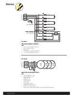
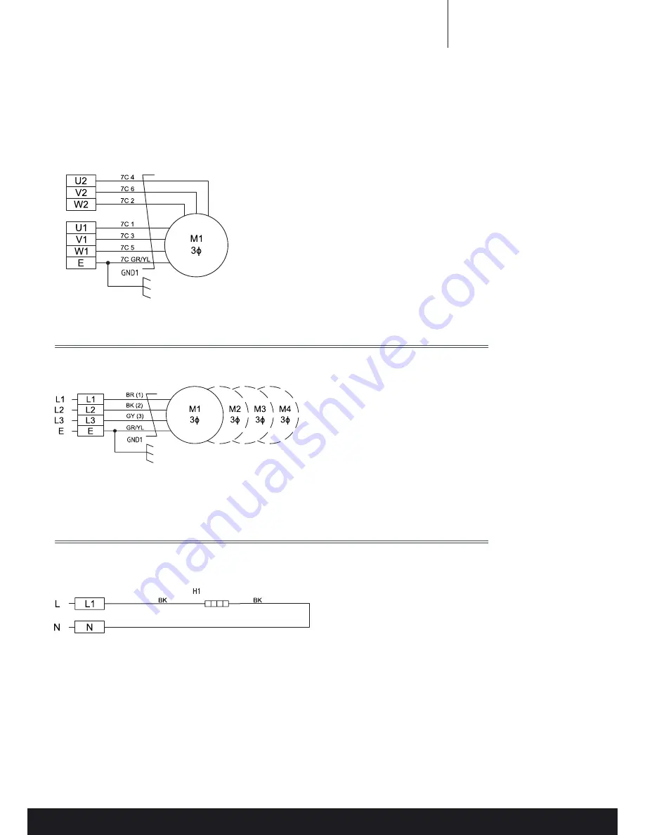
Wiring diagrams for FM
FM 20 to 36 (2 SPEED FAN)
Note:
1.
Fan supply 400v - 3ph - 50hz.
2. Applies to FM range only.
3. 2 Speed option only.
4.
For heater arrangement:
•
Ref. Drg. 271-112-211 or/
•
Ref. Drg. 271-112-215.LV
(As applicable).
5. Terminal box: 218-143-202.
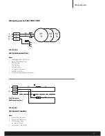
FM 20 to 36 (4 FAN SUPPLY)
Note:
1.
Fan supply 400v - 3ph - 50hz.
2. Applies to FM range only.
3. Common fan junction box.
4.
For heater arrangement:
•
REF. DRG. 271-112-215 or/
•
REF. DRG. 271-112-215.LV
(As applicable).
5. xTerminal box: 218-143-202.
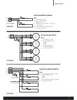
FM/SM Peripheral heater
Note:
1.
Supply 230v - 1ph - 50hz.
2. Applies to FM/SM range only.
3. For fan arrangement:
•
REF. DRG. 271-112-213 or
•
REF. DRG. 271-112-215-LV or
•
REF. DRG. 271-112-215
4.
Terminal Box(S): 218-143-101.
5. Option Dual Phase Peripheral
6. Heater Connected To L1 And L2.
271-112-210
271-112-211
271-112-214


