background image

23

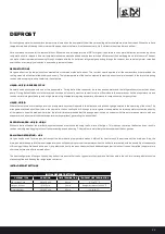
DEFROST

Air cooling evaporators whose surface temperature is lower than the dew point of the air they are cooling will accumulate moisture from the air.  When the surface 

temperature is below freezing, this moisture will be deposited in the form of frost and eventually, if left, will restrict heat transfer and air flow.

Various methods are used for the removal of frost.  When the air inlet temperature is at 38°F or higher it is possible to use natural defrost by just switching off the 
refrigeration flow for a period.  At lower temperatures heat needs to be added and the fans switched off to prevent the heat being blown into the store. The heat 
can be from electrical elements passing through or adjacent to the fin, hot/warm refrigerant gas passing through the tubes or, less commonly, water cascaded 
over the fins or a warm glycol solution in a secondary system of tubes.

DEFROST OPTIONS

Hot-gas defrost can be the quickest and most efficient common method of defrost.  The fact that heat is applied to all the same surfaces that provided the                 

cooling means that frost is melted quickly and evenly.  The low temperature of the heat, compared to electric defrost, results in less heat, in the form of steaming                      
condensate, escaping from the cooler into the cold store.

HG(E)A, HG(E)B – REVERSE CYCLE

Generally used on systems with one or two evaporators.  During defrost the condenser is used as an evaporator and the refrigeration system acts as a heat 

pump.  During defrost the flow is in the reverse direction as it is usually most convenient to redirect flow close to the compressor.  As the evaporator acts as a 

condenser in this regime the hot gas is at high pressure/high temperature giving a superior performance in comparison to a hot gas system.

HG(E)C, HG(E)D

Where there are two or more evaporators on a refrigeration system it is possible to defrost one using the hot-gas generated in the operating of the other. This 

arrangement allows defrost flow to be in the same direction as cooling flow.  Although this arrangement can operate on a two evaporator system the quantity 

of low pressure, super heated gas is minimal, therefore it is recommended that this arrangement is used on systems with three or more evaporators, with one 
evaporator on defrost whilst the other evaporators are operational, generating the defrost heat.

DEFROST HEADER - HG(E)B, HG(E)C

Without a defrost header the distribution system causes a restriction reducing the flow rate of hot-gas.  This reduces the rate of defrost and can result in                          

condensed refrigerant logging in the coil and preventing even defrosting.  This problem is more likely the less superheat the hot-gas has.

DRAIN PAN DEFROSTING – HGE

Hot gas can be used for drain pan defrost but the lower heating temperature makes it difficult for heat to reach the extremes of the drain-pan. Also, the                           

drain-pan is more exposed to the room temperature and will quickly drop to room temperature when the defrost is terminated, with the possibility of condensate 
still running of the coil to freeze in the pan.  Using electric defrost in the pan overcomes these disadvantages, particularly as it can be controlled to operate for a 
short time before and after the main defrost.

The best configuration of hot gas coil and tray defrost is to ensure that the hot gas enters the tray matrix first then enters the coil, this is arranged via the valve 
station supplied and fitted by the refrigeration contractor.  

INITIAL DEFROST SETTINGS 

INITIAL DEFROST SETTINGS

DEFROST TYPE

DURATION

TIME TERMINATION

TEMPERATURE TERMINATION

Off cycle defrost

20 to 30 min

45 min

4.5 to 7.2 °C

Hot gas defrost

10 to 15 min

20 min

Refrigerant pressure at 25 °C

Electric defrost

30 to 45 min

45 min

10 to 12.7 °C

Summary of Contents for TEC1

Page 1: ...Kelvion Commercial Coolers INSTALLATION MAINTENANCE Health Safety Warranty Procedure Parts Spares Dimensions Weight Installation Fanset Wiring Control options CONTENT KG...

Page 2: ...PROTECTIVE CLOTHING Sharp edges on the casework of the units and coil fins are a possible cause of cuts to fingers and hands Appropriate protective clothing gloves should always be worn ENSURE THAT T...

Page 3: ...l be advised and further instructions requested either to return the item or to issue an official order to replace or rectify the item If you require a replacement product the buyer will be asked to s...

Page 4: ...TEC SPARES PARTS DIMENSIONS 15 378mm Casework TEC1 TEC5 TEC7 8 210mm 3 4 D CONN TEC1 TEC5 TEC7 15 378mm Casework 10 260 5mm 3 4 D CONN A Casework B C...

Page 5: ...ment 425W 2 215 260 401 100461664 WT3 5 4 LTKIT Defrost Element 575W 2 215 260 601 100461668 WT5 LTKIT Defrost Element 675W 2 215 260 701 100461671 WT6 LTKIT Defrost Element 470W 4 215 415 001 1004617...

Page 6: ...ORIFICE FIT FANSET M4 FIXINGS 4 PER FAN MONOBOLT FAN PLATE TO BOTTOM PLATE 5 OFF MONOBOLTS ALUMINIUM RIVETS TO BE USED TO FIX BOTTOM PLATE DRAIN PAN FITTED LOOSE FOR TRANSPORT PLACE 4 x M6 FIXINGS IN...

Page 7: ...30 KEC35 40 45 DRAIN PAN CASE 1500 19 040 100458835 KEC55 70 TABLE A UNIT FAN SET SAP NUMBER J BOX SAP NUMBER KEC10 231 9030 0121 100464214 218 901 013 100462723 KEC15 231 9030 0121 100464214 218 901...

Page 8: ...5 409 5 555 574 9 KME SPARES PARTS DIMENSIONS 60 MOUNTING CTRS 17 5 A MIN KME 50 175 146 B O A D D PAN COIL CONNS END 1 D CONN ELEC CONNS END C MOUNTING CTRS 146 53 MOUNTING BRACKET DETAIL SLOT 13W X...

Page 9: ...HT A B C D 6 FPI 4 FPI 3 FPI KME50 350mm 1007mm 715mm 1011mm 2 1Kg 85Kg KME60 350mm 1332mm 1040mm 1336mm 2 9Kg 112Kg KME80 400mm 1682mm 1390mm 1686mm 2 6Kg 129Kg KME95 450mm 1682mm 1390mm 1686mm 3 9Kg...

Page 10: ...ution labels 3 Pass label 4 Name Plate 5 Plate label Fork lift points K Kelvion elvion KEC30 4L 44L L1Ph S3G PI 1 Maximum operating pressure suitable for this product 2 Electrical supply information 3...

Page 11: ...11 Keepdry Thiswayup Fragile Recycle Stacking 3...

Page 12: ...intrayalongthesideoftheunit 3 Placeintopositionusingthelocationguidance UNPACKINGONALLTECMODELS Thelocationoftheunitshouldbecarefullyselectedtoensurethat 4 Air distribution from the cooler is not adve...

Page 13: ...ingmustbeinaccordancewithgoodrefrigerationpractice 2 Airenteringthecoolerisnotobstructed 3 Theunitmustbeinstalledlevelinbothdirections 4 Maintenanceaccessshouldbeconsideredwhenlocatingtheproduct inclu...

Page 14: ...Nut 1 O D Washer MOUNTINGTHEUNIT Evaporator Mounting Bracket 1 O D Washer Nut 1 5 8 O D Washer Products A Free air discharge 1 4 ft drop per ft Trap Door and air curtain Seal Required Drain...

Page 15: ...tor Airstreamshouldbeunobstructedbybeams lightsorotherstoreproducts generallydownaislestowardsthedoor Evaporatorsaredesignedtobeflushandlevelceilingmounted Mountingrodsandsupportstructureshouldbedesig...

Page 16: ...re necessary Dry nitrogen should be passed through the pipework during brazingtominimiseoxidisation WARNING UseappropriatePPE personalprotectionequipment duringpipework refrigerantchargingandcommissio...

Page 17: ...R MANIFOLDCAPS Iftheholdingchargeisnotpresentthemanufacturershouldbecontactedimmediately Unitsthathavebeenpackedincardboardmustbestoredinadryenvironmenttopreventanywaterdamage DAMAGECAUSEDBYINCORRECTI...

Page 18: ...with a bush or grommet Unitelectricalschematicissecuredtotheinsideoftheterminalboxorendcover MOTORS AllmotorsareEC electronicallycommutated andwiredtotheterminalbox Wiresarefixedtoascrewor cageclamp t...

Page 19: ...tSupplyTo TerminalBlockTerminals1andN 4 Lowspeed Linkterminalblock terminals1 2 5 Defrostheaters Ifrequired TerminalBox 218 901 013 271 111 145 KEC10 15 20 25 30 FAN DEFROST NOTE 1 Supply230V 1PH50 60...

Page 20: ...als1 2 5 Defrostheaters ifrequired 6 TerminalBox 218 901 015 271 111 147 KEC35 40 45 55 70 FAN DEFROST NOTE 1 FansSupply230V 1PH50 60Hz 115V 1PH50 60Hz 2 DefrostHeatersSupplyOption 3 230V 1Ph 50Hzor40...

Page 21: ...111 125 4 TerminalBox S 290 660 W 290 661 W KME50 175 1PHASEFANSUPPLY NOTE 1 FanSupply230V 1PH50 60Hz 115V 1PH50 60Hz 2 AppliesToUKMERangeOnly KME50 601Fan KME80 952Fans KME115 1403Fans KME1754Fans 3...

Page 22: ...x s 290 668 W 290 661 W 6 Warning onlysuitablefor3 phaseandneutralconnection KME50 175 3PHASEFANSUPPLY NOTE 1 FanSupply480V 3PH50 60Hz 2 AppliesToKMERangeOnly KME50 601Fan KME80 952Fans KME115 1403Fan...

Page 23: ...ere there are two or more evaporators on a refrigeration system it is possible to defrost one using the hot gas generated in the operating of the other This arrangement allows defrost flow to be in th...

Page 24: ...1 3rd of the way along the coil face air on and about 2 3rdsupawayfromanyheaterelements Oncethesystemisinoperationitmaybenecessarytorelocatetheprobetotheareaofthecoilwhereiceremainsthe longestduringde...

Page 25: ...ely Electricalconnectionsforsecurityofattachment Checkallexternalsurfacesannuallyforanycorrosionorpeeling Cleananyaffectedareathoroughlywith awirebrush applyacoatofzincprimerandretouchwithasuitablefin...

Page 26: ...tobedecidedbythehygienemanagementoftheenduserandtobeappropriate tothetypeofproductintheroom Themostimportantissueapartfromthereductionofbacteriawithinthecasingistoreducethecorrosionpotential cleaningi...

Page 27: ...e EN60204 1 1999Safetyofmachinery Electricalequipmentofmachines BSEN61032 1998Protectionofpersonsandequipmentbyenclosures Probesforverification propellerfanunits BSEN13857 2008Safetyofmachinery Safety...

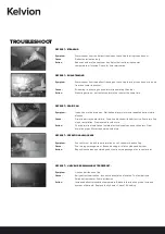
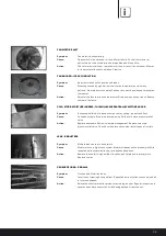
Page 28: ...in line or tray heater failure Drain line blocked with debris or ice Poor drain line slop or installation Trap located in cold store Action Check drain line installation Isolate electrical supply and...

Page 29: ...om Excessive build up of ice and snow on cooler ceiling product and floor Cause Failed door seals Excessive door opening Failed cold store pressure relief valve Action Replace door seals Review cold s...

Page 30: ...www kelvion com Copyright Kelvion Cooler Manual Sep 2020...

Reviews: