16
E. Start-Up Instructions
E-1 Control Box
The unit is switched on and off via the switch on the bottom right of the control box. A green
indicator lamp shows that the unit is in operation. The control box also houses the electrical
components of the available accessories.
Only for units with 3-phase fans:
When starting up for the first time, switch the unit on at the control box, then switch off again
immediately.
Check the direction in which the fan is still rotating to see if it matches the arrow on the fan
housing. The blades must turn in the direction of the exhaust outlet.
If the rotation direction is wrong, change two phases (black) on the motor terminals.
E-2 Safety Isolator Switch
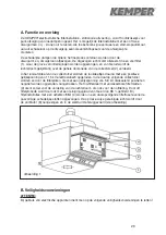
Please open the service door while the unit is in operation to check the safety isolator switch.
The fan must switch off and indicator lights "2" and "3" must go out.
Caution:
This test serves only to check the funcitioning of the safety isolator switch. In principle, however,
the unit must be switched off before the service door is opened.
E-3 High-Voltage Monitoring
The unit has an electronic high-voltage monitoring unit. Malfunctions in the high-voltage section
are reported to the operator via illumination of the red indicator lamp in the black panel on the
filter unit. The green lamp lights up during normal operation.
E-4 Correct Adjustment
Position the exhaust arm in a way that the intake hood is about 30 to 50 cm above the welding
area.
Summary of Contents for 150 0002
Page 2: ......
Page 53: ...51 I 5 Filterüberwachung Filter Monitor Contrôle de saturation ...
Page 54: ......
Page 55: ......
Page 56: ......

