background image

Safety Measures

DX,LOWER -19-24FEB00-1/1

DX,PAINT -19-24JUL02-1/1

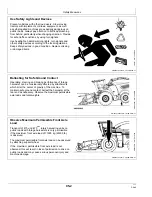
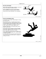
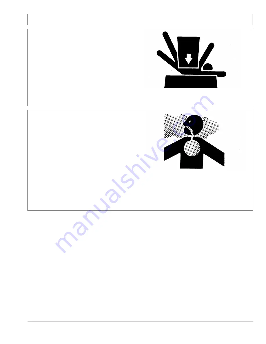
Support Machine Properly

Always lower the attachment or implement to the ground
before you work on the machine. If the work requires
that the machine or attachment be lifted, provide secure
support for them. If left in a raised position, hydraulically
supported devices can settle or leak down.

Do not support the machine on cinder blocks, hollow tiles,
or props that may crumble under continuous load. Do not
work under a machine that is supported solely by a jack.
Follow recommended procedures in this manual.

When implements or attachments are used with a
machine, always follow safety precautions listed in the
implement or attachment operator's manual.

TS229

—UN—23AUG88

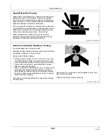
Remove Paint Before Welding or Heating

Avoid potentially toxic fumes and dust.

Hazardous fumes can be generated when paint is heated
by welding, soldering, or using a torch.

Remove paint before heating:

Remove paint a minimum of 100 mm (4 in.) from area
to be affected by heating. If paint cannot be removed,
wear an approved respirator before heating or welding.

If you sand or grind paint, avoid breathing the dust.
Wear an approved respirator.

If you use solvent or paint stripper, remove stripper with
soap and water before welding. Remove solvent or
paint stripper containers and other flammable material
from area. Allow fumes to disperse at least 15 minutes
before welding or heating.

Do not use a chlorinated solvent in areas where welding
will take place.

TS220

—UN—15APR13

Do all work in an area that is well ventilated to carry toxic
fumes and dust away.

Dispose of paint and solvent properly.

05-7

031318

PN=13

Summary of Contents for 400F Support Wheel

Page 1: ...400F Support Wheel OMKM113756 OPERATOR S MANUAL 400F Support Wheel OMKM113756 ISSUE C8 ENGLISH Maschinenfabrik Kemper GmbH Co KG European Edition PRINTED IN U S A...

Page 2: ...he identification numbers in a secure place away from machine BEFORE DELIVERING THIS MACHINE your dealer performed a predelivery inspection INTENDED USE THIS SUPPORT WHEEL MUST BE USED EXCLUSIVELY to...

Page 3: ...cking Status Indicator 15 4 Page Detaching Detach Support Wheel 20 1 Support Wheel Operation Observe Maximum Permissible Front Axle Load 25 1 Driving on Roads Claas Forage Harvesters 25 1 Driving on R...

Page 4: ...Contents ii 031318 PN 2...

Page 5: ...irst time adjust the position of the locking device Advise the customer of the proper weights and fluids that must be used in the tires depending upon forage harvester Check if all safety shields are...

Page 6: ...Identification View KM00321 000041A 19 07APR15 1 1 Identification View KM240691 UN 07APR15 00 1 031318 PN 6...

Page 7: ...dealer Before you start working with the machine learn how to operate the machine and how to use controls properly Do not let anyone operate without instruction Keep your machine in proper working co...

Page 8: ...ing for Safe Ground Contact Operating steering and braking performance of forage harvester can be considerably affected by attachments which alter the center of gravity of the machine To maintain safe...

Page 9: ...tions Always observe local road traffic regulations when using public roads H28930 UN 30JUN89 Prevent Machine Runaway Avoid possible injury or death from machine runaway Do not park machine on a slope...

Page 10: ...road travel This ensures that all the hydraulic functions with the exception of the steering and the return to pressure are switched off A Switch for Road Field Mode KM1002285 UN 27FEB18 Claas Forage...

Page 11: ...eel nuts Torque 350 Nm 258 lb ft KM1000918 UN 29JUL09 Prepare for Emergencies Be prepared if a fire starts Keep a first aid kit and fire extinguisher handy Keep emergency numbers for doctors ambulance...

Page 12: ...eep hands feet and clothing from power driven parts Disengage all power and operate controls to relieve pressure Lower equipment to the ground Stop the engine Remove the key Allow machine to cool Secu...

Page 13: ...29 UN 23AUG88 Remove Paint Before Welding or Heating Avoid potentially toxic fumes and dust Hazardous fumes can be generated when paint is heated by welding soldering or using a torch Remove paint bef...

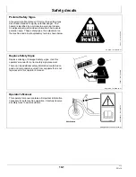
Page 14: ...lacement on the machine and a brief explanatory text are shown below TS231 19 07OCT88 Replace Safety Signs Replace missing or damaged safety signs Use this operator s manual for correct safety sign pl...

Page 15: ...09 1 1 KM00321 00001CA 19 29JUL09 1 1 Front Wheel Attaching Nuts Retighten wheel attaching nuts at specified intervals KM1000920 UN 28SEP12 Support Wheel Observe an adequate distance to support wheel...

Page 16: ...vester software so that the return to pressure hydraulic system may be controlled when in road mode The impulse for support wheel identification is triggered as soon as the electrical wiring harness o...

Page 17: ...d up locking pawls A closed Rotary harvesting unit folded out locking pawls A opened Attach Support Wheel NOTE If rotary harvesting unit cannot be unfolded as described above due to lack of space supp...

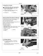
Page 18: ...e position of the locking device must be adjusted Correct locking device position Between the top position of the open locking pawl A and approx 3 mm below the top position Adjustment procedure Lift r...

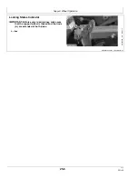
Page 19: ...UN 25MAR15 3 Folding of the rotary harvesting unit will lock the support wheel automatically KM239226 UN 16AUG17 Locking Status Indicator NOTE The extension of rod A indicates whether locking device i...

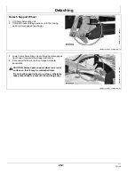
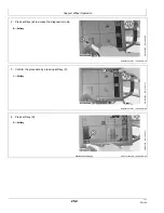
Page 20: ...wn KM239228 UN 26MAR15 3 Lower rotary harvesting unit until feed bar disengages from hook of support wheel see illustration 4 Park support wheel and drive forage harvester backwards CAUTION Always par...

Page 21: ...on public roads CAUTION Transport of 475 and 475plus rotary harvesting units on public roads with forage harvesters is only permissible if the maximum front axle load of 11500 kg 25353 lb is observed...

Page 22: ...pport wheel identification A lights up red Support wheel identified ready for speeds up to 20 km h If the icon for support wheel identification lights up green Support wheel identified ready for speed...

Page 23: ...them with rubber ropes Support wheel is now ready for operation A Protective curtains KM239239 UN 27MAR15 Driving on Roads Fendt Forage Harvesters Before driving on roads press button A This activate...

Page 24: ...4 8 Continued on next page KM00321 0000421 19 08APR15 5 8 2 Press softkey B to access the diagnostic mode B Softkey KM1002368 UN 26SEP13 3 Confirm the procedure by pressing softkey C C Softkey KM1002...

Page 25: ...371 UN 30SEP13 6 Check whether the support wheel has been recognized by the harvester s software IMPORTANT Message F must be accompanied by a tick check mark F Message KM1002372 UN 30SEP13 7 Install c...

Page 26: ...KM00321 0000183 19 22MAY12 1 1 Locking Status Indicator IMPORTANT Before every road journey make sure that the support wheel is locked and that rods A are extended at both sides A Rod KM1002289 UN 21...

Page 27: ...ype 497a 4 Rear axle load minimum 6640 kg 14638 lb installed Jaguar 950 960 Type 497b 4 Rear axle load minimum 6670 kg 14705 lb installed Jaguar 970 Type 497a 3 Rear axle load minimum 7180 kg 15830 lb...

Page 28: ...a wheel and tire assembly The heat can cause an increase in air pressure resulting in a tire explosion Welding can structurally weaken or deform the wheel When inflating tires use a clip on chuck and...

Page 29: ...5 0 55 17 14 PR Width 391 mm 15 39 in Diameter 850 mm 33 46 in Tire Inflation Pressures NOTE The tire inflation pressures quoted in the table refer to the permissible axle load of 2000 kg 4409 lb of t...

Page 30: ...in locking pawl Repeat attaching procedure Locking mechanism adjusted incorrectly Adjust locking mechanism Support wheel is not identified Wiring harness of rotary harvesting unit not connected to fo...

Page 31: ...ners or for nuts on U bolts see the tightening instructions for the specific application Tighten plastic insert or crimped steel type lock nuts by turning the nut to the dry torque shown in the chart...

Page 32: ...cification NLGI Service Classification GC LB IMPORTANT Some types of grease thickeners are not compatible with others Contact your lubricant supplier before mixing various types of lubricants KM100089...

Page 33: ...1 1 Every 50 Hours Wheel Bolts Retighten wheel bolts Specification Wheel bolt Torque 240 Nm 177 lb ft KM1000944 UN 11AUG09 Every 50 Hours Swivel Lubricate with grease KM1000946 UN 11AUG09 Every 50 Ope...

Page 34: ...only if the support wheel is NOT recognized by the forage harvester software 1 Take out screw A and pull out locking status indicator B from above A Screw B Locking status indicator KM240685 UN 02MAR1...

Page 35: ...19 02MAR18 3 3 5 Insert the preset sensor unit Using slot holes A adjust the sensor unit such that dimension X 17 mm 0 67 in is set at the bottom end of the rod A Slots X 17 mm 0 67 in KM240688 UN 02...

Page 36: ...t provisions and essential requirements of the following directives DIRECTIVE NUMBER CERTIFICATION METHOD Machinery directive 2006 42 EG Self certification per Article 5 of the Directive Agricultural...

Page 37: ...n Number D Weight E Year of Manufacture F Model Year G Permissible Front Axle Load KM1002302 UN 15MAY12 Serial Number When ordering parts always quote the support wheel serial number The serial number...

Page 38: ...Serial Number 55 2 031318 PN 38...

Page 39: ...ving on roads Claas forage harvesters 25 1 Fendt forage harvesters 25 3 G Grease Extreme Pressure and Multi Purpose 45 2 H Hardware torque values Metric 45 1 I Identification view 00 1 Page L Locking...

Page 40: ...Index Index 2 031318 PN 2...

Reviews: