Attaching
KM00321,000016E -19-09MAY12-1/1
KM00321,000016F -19-21MAY12-1/1
Continued on next page
KM00321,0000402 -19-25MAR15-1/3
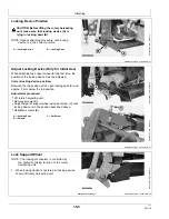
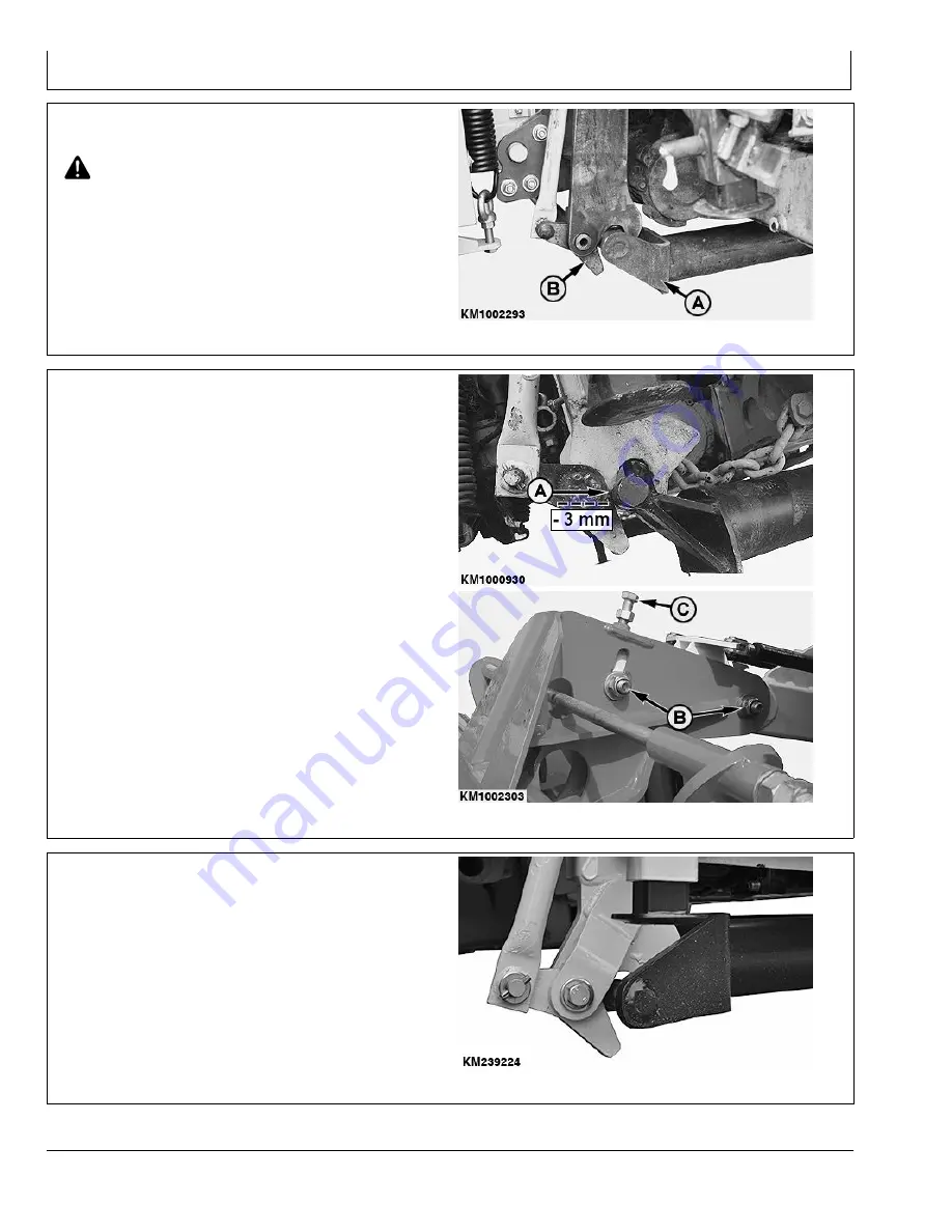
Locking Device Position
CAUTION: Before lifting the rotary harvesting
unit, make sure that locking device (A) is
lying in locking pawl (B).
NOTE: Repeat attaching procedure until locking
device is in the correct position.
A—Locking Device
B—Locking Pawl
KM1002293
—UN—15MA
Y12
Adjust Locking Device (Only for Initial Use)
When attaching the support wheel for the first time, the
position of the locking device must be adjusted.
Correct locking device position:
Between the top position of the open locking pawl (A) and
approx. 3 mm below the top position.
Adjustment procedure:
•
Lift rotary harvesting unit.
•
Remove screws (B).
•
Adjust height of support wheel using set screw (C) until
locking device is in the position described above.
•
Retighten screws (B).
A—Locking Pawl
B—Screws
C—Set Screw
KM1000930
—UN—30JUL09
KM1002303
—UN—21MA
Y12
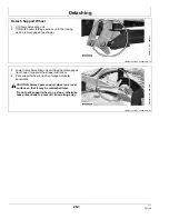
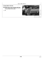
Lock Support Wheel
NOTE: The locking mechanism is controlled by
the hydraulic folding function of the rotary
harvesting unit.
1. When locking device is centered in locking pawl as
shown, lift rotary harvesting unit.
KM239224
—UN—25MAR15
15-3
031318
PN=18
Summary of Contents for 400F Support Wheel
Page 4: ...Contents ii 031318 PN 2...
Page 38: ...Serial Number 55 2 031318 PN 38...
Page 40: ...Index Index 2 031318 PN 2...


