background image

Summary of Contents for Dusty

Page 1: ...KEMPER Dusty Part No 150 0471 ...

Page 2: ......

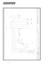
Page 3: ...ation 4 5 Emptying of the Dust Collection Container 5 6 Cleaning of the Filter Cartridge 6 7 Replacement of Carbon Brushes 7 8 Fastening of the Filter Unit 7 9 List of Spare Parts 8 10 Technical Specification 8 11 Drawing 9 12 European Community Declaration of Conformity 10 13 Troubleshooting 11 14 Wirering Diagrams 12 15 ...

Page 4: ...lease read through and take notice of the following instructions before operating the machine Keep the operation and maintenance manual handy Protect the connecting cable against heat oil and damages by sharp edges The power line regularly has to be examined for indications of damages The filter unit should not be used if the status of the power line is not acceptable Take care of the correct volt...

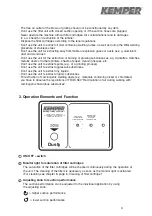
Page 5: ...Don t use the unit to extract organic substances For extraction of carcinogenic welding dusts e g materials containing nickel or chromates you have to observe the regulations of TRGS 560 Recirculation of air during working with carcinogenic hazardous substances 3 Operation Elements and Function ON OFF switch Monitor light for saturation of filter cartridges The saturation of the filter cartridges ...

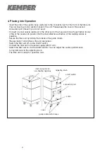
Page 6: ...ition that the most effective extraction of the welding smoke is possible Secure the filter unit by locking the brakes at the guide rollers Please check if all catches at the unit are locked Switch the filter unit off via the On Off switch Connect the filter unit to the power supply 230 V AC Switch the filter unit on via the On Off switch You can adjust the suction performance to any demand via th...

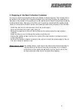
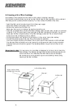
Page 7: ...ect it from the power supply Open both catches at the lower side of the unit Remove the upper part of the unit with the filter and the turbine inside the dust collection container Make sure that you do not damage the sealing around the unit Dispose the welding smoke dust which is inside of the dust collection container according to legal regulations Remount the cleaned collection container to the ...

Page 8: ...artridge is cleaned The air stream should be blown onto the cartridge from top to bottom Put the turbine back onto the filter unit and fasten it to the unit by closing the catches Connect the power supply to the unit The unit is ready for operation You have to repeat cleaning of the filters if the monitor light for filter saturation is still activated The saturated filter cartridge must not be cle...

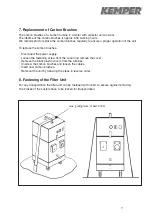
Page 9: ...shes Disconnect the power supply Loosen the fastening screw from the cover and remove the cover Remove the black plastic covers from the turbines Unscrew the carbon brushes and loosen the cables Insert new carbon brushes Remount the unit by following the steps in reverse order 8 Fastening of the Filter Unit For any transportation the filter unit can be fastened with a belt to secure against removi...

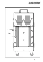
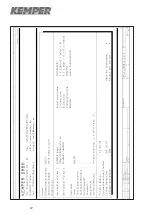
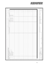
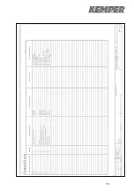
Page 10: ...switch Monitor switch for filter saturation red 230 V Monitor switch for filter saturation red 115 V Speed frequency control 230 V Speed frequency control 115 V Micro fuse 10 A time lag Micro fuse 20 A time lag Pressure differential switch Suction turbine 230 V AC Suction turbine 115 V AC Guide roller Guide roller lockable Power cable 230 V Item 1 2 3 4 5 6 7 8 9 10 11 12 13 14 15 Part No 109 0244...

Page 11: ...9 ...

Page 12: ... and 96 44 EWG European Community machine standard 89 336 EWG and 92 31 EWG EMV standard version 87 404 EWG and 90 488 EWG Regulation for compressed air reservoirs 73 23 EWG Regulation for low voltage 93 68 EWG Regulation for labelling Applicable harmonized standards especially EN 292 part 1 and part 2 Security of machinery EN 50081 part 1 Law referring to the electromagnetic Transmission of devic...

Page 13: ...ween filter cartridge and filter housing Holes in the filter cartridge Troubleshooting Connect the filter unit to the power supply Check if the power cable has been plugged into the socket properly Replace power cable Replace fuse in the fuse carrier at the inlet connector for non heating apparatus Remove the cover plate from the adjusting knob and refasten the fixing bout of the adjusting knob Cl...

Page 14: ...12 ...

Page 15: ...13 ...

Page 16: ...14 ...

Page 17: ...15 ...

Page 18: ......

Page 19: ......

Page 20: ......

Reviews: