©
www.kemper-olpe.de
– 11.2021 / K410068602012-00 – 27/ 32
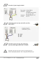
Connection of valve V1
Terminal item 4 and 6
2.5
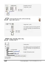
Connection KHS Drain with overflow monitoring
Figure 688 00 | 684 04
Terminal item 7 and 8
The controller is preset for connecting the KHS
Free drain. The bridge on Terminal IN3 must be
removed.
2.6
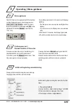
Using a floating alarm relay,
terminal item 9
Terminal item 9
The controller is preset for connecting the KHS
Free drain. The bridge on Terminal IN3 must be
removed.
Example: Closing relay version
Extrenal voltage
max. 230 V, 2 A
e.g. indicator light
e.g. Input BMS or alarm system
BN = brown
WS = white
BN = brown
WS = white
e.g. alarm horn
BU
BN
BN
WS
N
N


