Service manual Mastercool 30
Version 1.0
1.11.2011
7
Kemppi Oy
3.4. Description of operation
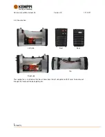
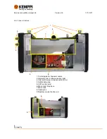
Mastercool 30 can be divided to three parts: A001 control card, pump with motor and water circulation
components.
Note that Mastercool has had two different principles for pressure dampening and three different types of
control cards depending the manufacturing time.
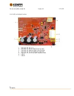
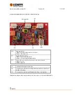
3.4.1. A001 control card
•
Control card controls the pump start and stop. This is made by the start signal of power
source control card.
•
It monitors the water temperature. PTC resistor is +60 degrees of Celsius.
•
A001 card monitors water pressure by measuring the pump current. If pressure goes
over or under the limit card give fault-signal to power source via X3-1
•
Card controls cooling fan. Its start is related to pump running and has shut down delay
•
Card has several jumpers to activate alternative characteristic functions in problem
cases. Jumpers are described in next chapter.
3.4.2. Pump-motor assembly
•
Pump works by membrane principle (like piston) and can develop up to 10 bar pressure.
This is limited electronically to 5 bars to avoid internal damage and to protect water
hoses. Motor runs piston that moves the membrane. Membrane develops pressure that
is hold with two pressure valves. Piston type movement has a vibration as a side effect
and it must be filtered with damper. Pump can have water flow up to 0,8l/min.
•
Pressure valves keep the pressure high and water flow in right order
•
Motor runs the membrane pump piston. It uses v5,2VDC.
•
Pump input is connected to the copper pipe from the tank and output has integrated
spindle for output water hose.
•
Note that motor should be connected to A001 control card with two wires with flat
connectors X7 and X8. If old connection (A001 X4) is used with motor wires, it should be
replaced.
3.4.3. Water circulation components (Radiator, water hoses, tank and pressure damper system)
•
Radiator cools the heated water while it runs through it.
•
Tank holds the cooling liquid and the volume is approximately 3 liters.
•
Via Output water hose the cooling liquid runs to the snap connector.
•
Pressure damper system:
o
Dual type Water hose works as a pressure damper in old coolers
manufactured up to 4/2010. Inner hose was made of silicon to enlarge and
diminish when pressure changes. Outer hose was made of reinforced rubber
to limit the enlarging inner silicon hose. Together these makes generation 1
pressure damper system.


