background image

1

Service manual

Mastertig MLS 2300 ACDC

Version 1.3.1

Summary of Contents for MasterTig MLS 2300 ACDC

Page 1: ...1 Service manual Mastertig MLS 2300 ACDC Version 1 3 1...

Page 2: ...0 A 26 0 V 4 8 kVA 100 ED 120 A 24 8 V 3 7 kVA Supply cable fuse 2 5 mm S 3 3 m 16 A slow Adjustment range TIG 3 A AC 5 A 10 0 V 230 A 19 2 V MMA 10 A 20 4 V 180 A 27 2 V Maximum welding voltage 32 V...

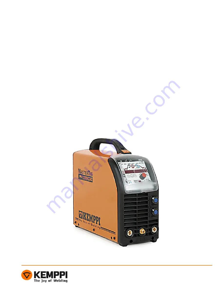
Page 3: ...5 6 1 Gas connector for TIG torch 2 Welding current connection negative 3 Operation panel 4 Remote controller connection 5 TIG torch control connection 6 Welding current connection positive 7 Main sw...

Page 4: ...off by a quick press on the start switch OFF Quick press on the start switch has no function Tacking automatics A9 ON Tacking automatics is ON no downslope if the weld is shorter than 3 s OFF Tacking...

Page 5: ...0 activation A16 ON Auxiliary switches are always active OFF Auxiliary switches are active only when torch control is selected Cooling unit flow control A17 ON Flow control is active OFF Flow control...

Page 6: ...the panel but keeps memory channels ALL Recalls factory settings and empties the memory channels Downslope interruption upslope angle B6 1 Upslope speed maximum 2 According to the upslope setting 3 A...

Page 7: ...tment range 9 minimum overrun 9 maximum overrun Start current level B13 10 Factory setting 10 of the welding current OFF Minimum current 5 4 0 Adjustment range 5 40 of the welding current Display reco...

Page 8: ...nge 0 10 s AC balance minimum C16 80 Factory setting 80 80 10 Adjustment range 80 10 Pregas time maximum D1 1 Factory setting 1 s 0 1 0 Adjustment range 0 10 s Postgas time maximum D7 30 Factory setti...

Page 9: ...100 500 Limited by the max of the power source Positive ignition current E6 50 Factory setting 50 30 150 Adjustment range 30 150 Limited by the max of the power source Positive ignition sequence time...

Page 10: ...ry setting 50 10 90 Adjustment range 10 90 MIX TIG DC level E11 100 Factory setting 100 50 150 Adjustment range 50 150 Spotwelding time E12 10 Factory setting 10 ms 1 2 00 Adjustment range 1 200 ms Se...

Page 11: ...11 Construction Z004 A004 A002 A001 Z002 Z001 behind the isolator Z003 A003 T001 T002 L001...

Page 12: ...12 Main circuit diagram...

Page 13: ...ontrol Error code Description Err 3 Over Undervoltage Err 4 Overheating Err 6 Internal fault secondary voltage over the limit Err 8 Maximum overheat time machine doesn t cool down fast enough Only mac...

Page 14: ...s are parallel connected discrete IGBTs 30A 600V The current transformer T1 measures the primary current Note IGBTs V12 V14 and V9 V11 are insulated from the heat sink Primary inverter s operating fre...

Page 15: ...15 Main circuit card Z001 Connectors X8 X2 X8 Z004 X1 X7 X6 X5 X4 X3 X4 A001...

Page 16: ...mped by the PTC resistor R23 and relay K1 together The rectifier unit V1 rectifies the net voltage to DC which can fluctuate between 260 380 V Power supply to the power supply card A002 via connectors...

Page 17: ...001 EMI choke L002 Varistor R002 EMI filter Primary rectifier V1 IGBT transistor insulated from the heat sink Diodes V2 and V3 X2 and X4 control card A002 power supply 230 Vac Intermediate circuit cha...

Page 18: ...V16 V20 are insulated from the heat sink Damping circuits RC reduce the voltage stress of secondary diodes The machine size is coded by resistor R1 s value AC welding auxiliary pulses are developed fr...

Page 19: ...19 Secondary rectifier Z002 Connectors X6 X5 X2 X1 X4 X3 X10 X9 X8 X7 X11...

Page 20: ...inverter card Z003 includes these following operational blocks Power supply for control circuits Gate control circuits Under voltage watches Secondary overvoltage protection Secondary inverter s power...

Page 21: ...21 Secondary inverter Z003 Connectors X6 X13 X18 X17 X16 X12 X11 X15 X14 X10 X5 X4 X2 X3 X1 X9 X8 X7 X19 X2 A001...

Page 22: ...nder voltage watch Over temperature watch Secondary inverter control Spark generator control Secondary voltage watch Secondary overvoltage watch X4 X5 X11 X9 X1 H6 H4 H7 H5 H3 X2 X3 X8 X7 X10 X6 X17 H...

Page 23: ...continuous 24 V and 15 V from main transformer T001 s auxiliary coils Flyback chopper About 20 V start power for the primary inverter s gate buffers Cooling unit 230 V power supply H1 H2 X3 X7 X9 X8...

Page 24: ...03 Spark card Functions and connectors HF spark card A003 includes these following operational blocks Voltage multiplier Spark on off control Spark voltage control X1 X3 X2 X3 R47 Spark voltage adjust...

Page 25: ...terface card Functions and connectors Filter card A004 includes following operational blocks Remote foot control interface TIG torch interface Panel interface Filtering of control lines X2 X1 X7 X6 X5...

Page 26: ...nsulator may damage the machine heavily To execute following low voltage tests Kemppi Multipower and wire set and digital multimeter is required Be very careful and follow the instructions set by step...

Page 27: ...X15 DC link negative Z004 heat sink DC link positive Z004 X4 24 VDC Measurements Jumper X12 A002 X2 and X4 230 VAC A002 X1 24 VDC 22VAC Z003 X9 Z003 X7 Gnd Negative dix Z003 X6 Copper rail Secondary h...

Page 28: ...to the main supply voltage 5 ERR 3 should appear if not machine cannot recognize the over under voltage state Connect jumper to the control card A001 jumper block X12 to mask off the Over under voltag...

Page 29: ...ions can be found on the Z004 card DC link positive in the heat sink via screw GND to the connector X15 7 Turn main switch to the OFF position 8 Switch on the Kemppi Multipower and connect the 230VAC...

Page 30: ...witch ON the Kemppi Multipower 3 Switch ON the machine 4 Set machine to the TIG mode 5 Touch to the machine terminals with tester wires 6 Machine will show Err 6 on the display if secondary voltage wa...

Page 31: ...heat sink Heat transferring paste is applied as thin layers on both sides of the insulators Absolutely no impurities are allowed on surface of the insulators when mounting them between the heat sink a...

Page 32: ...ansferring paste is applied as thin layers on both sides of the insulators Absolutely no impurities are allowed on surface of the insulators when mounting them between the heat sink and the IGBT Note...

Page 33: ...insulators Mica insulators have to be replaced always when the secondary diode card Z002 is separated from heat sink Heat transferring paste is applied as thin layers on both sides of the insulators A...

Page 34: ...have to be replaced every time the main circuit card Z003 is disconnected from heat sink Heat transferring paste is applied as thin layers on both sides of the mica insulators Absolutely no impuritie...

Page 35: ...35 Notes...

Reviews: