28
Measurements
Test 1: power state, main transformer and secondary rectifier
1.
Disconnect cooling fans.
2.
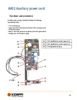
Auxiliary power supply card A002:
•
Disconnect wires from connectors X2 and X4 and connect 230 VAC connector to the X2
and X4 (Do not connect it to the main supply voltage). Use the wire delivered with the
multipower wire set.
•
Disconnect connector X1 and connect 24 VDC from Kemppi Multipower to the X1
(polarity is not important).
3.
Connect 50 VDC from Kemppi Multipower to the DC-link circuit. Measure DC-link voltage before
connecting PSU to the DC link. Voltage must be under 10VDC, otherwise it may destroy the Multipower.
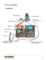
Connections can be found on Z004 card:
•
+50V to the heat sink via screw.
•
GND to the connector X15.
4.
Switch on the Kemppi Multipower and connect the 230VAC plug to the main supply voltage.
5.
ERR 3 should appear, if not machine cannot recognize the over/under voltage state. Connect jumper to
the control card A001 jumper block X12 to mask off the Over/under voltage detection.
6.
Set machine to the MMA mode.
7.
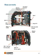
Measure voltages from following points (GND = minus terminal of machine):
•
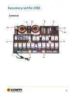
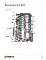
Z003 X7 voltage should be
approx
. +40V…+58V
•
Z003 X9 voltage should be
approx
. -40V…-58 V
•
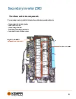
Z003 X6 (copper rail) voltage should be
approx.
-6…-10 V
•
Secondary heat sink voltage should be
approx
. +6V…+10 V
•
VRD machine has +22VDC
8.
If voltages are OK -> power stage is OK.
9.
Switch OFF the Kemppi Multipower and
disconnect 230VAC test wire main supply voltage plug
.
10.
Remove testing wires from DC-link (+50V in the heat sink screw and GND in the connector X15)
11.
If making Test 2. jump to Test 2 step 4 otherwise disconnect testing test wires.
12.
Connect back disconnected wires to the A002.
13.
Disconnect jumper from the control card A001 jumper block X12.
14.
Connect cooling fans
Next test
Summary of Contents for MasterTig MLS 2300 ACDC
Page 1: ...1 Service manual Mastertig MLS 2300 ACDC Version 1 3 1...
Page 11: ...11 Construction Z004 A004 A002 A001 Z002 Z001 behind the isolator Z003 A003 T001 T002 L001...
Page 12: ...12 Main circuit diagram...
Page 15: ...15 Main circuit card Z001 Connectors X8 X2 X8 Z004 X1 X7 X6 X5 X4 X3 X4 A001...
Page 19: ...19 Secondary rectifier Z002 Connectors X6 X5 X2 X1 X4 X3 X10 X9 X8 X7 X11...
Page 35: ...35 Notes...


