


Service manual Minarc Evo 150 and 180
Version 1.3
30.9.2015
9
Kemppi Oy
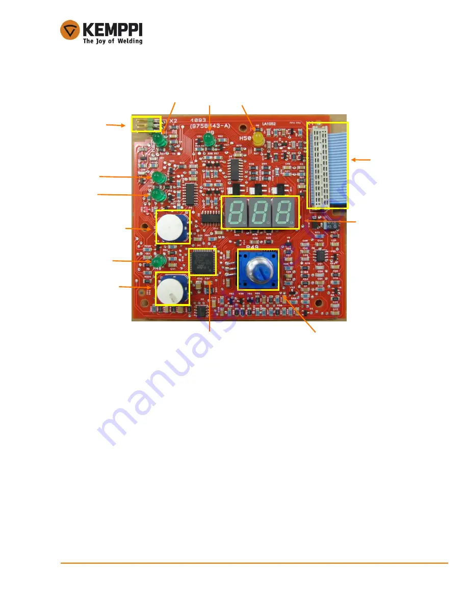
3.3.3. A001 control card structure
1. X2 service connector (not field programmable, serial bus
connection is in the primary side)
2.
MMA/TIG selection
3. Remote ON/OFF
4. Microcontroller
5. Analogic potentiometer
6. 7-segment display
7. X1 connector to main circuit card (flat cable)
8.
Overheat LED
9.
VRD LED
10. Welding machine ON LED
11. TIG mode LED
12. MMA mode LED
13. Remote ON LED
1.
2.
3.
4.
5.
6.
7.
8.
9.
10.
11.
13.
12.


