


Service manual Minarc Evo 150 and 180
Version 1.3
30.9.2015
21
Kemppi Oy
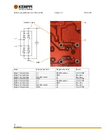
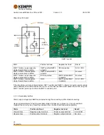
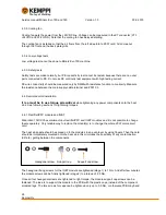
Minarc Evo 180 card:
IGBT
Positive test lead
Negative test lead
Result
IGBT 1 diode + upper separate
diode; forward bias condition
IGBT1 emitter/IGBT 2
collector
DC-link positive
0,2-0,7VDC
IGBT 2 diode + lower separate
diode; reverse bias condition
IGBT1 emitter/IGBT 2
collector
GND
No value
IGBT 1 diode + upper separate
diode; reverse bias condition
DC-link positive
IGBT1 emitter/IGBT
2 collector
No value
IGBT 2 diode + lower separate
diode; forward bias condition
GND
IGBT1 emitter/IGBT
2 collector
0,2-0,7VDC
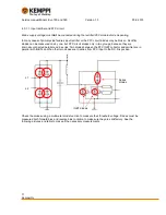
If the transformer primary is disconnected, IGBT 1 emitter and IGBT 2 collector connection points can be
used separately to measure diodes one by one. In this case the table must checked twice: first using the
IGBT 1 emitter point only and then the IGBT 2 collector point.
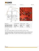
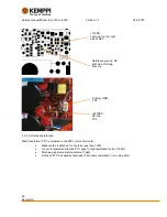
4.3.1.3. Secondary rectifier
Mains supply voltage must
not
be connected during the secondary rectifier diode measuring.
Use a digital multimeter to test the secondary diodes. Diodes are in groups, so it is not possible to
measure them one by one unless they removed from the board and measured separately.
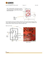
Diode
Positive test lead
Negative test lead
Result
Forward bias
Negative output terminal
Positive output terminal
0,2-0,6VDC
Reverse bias
Positive output terminal
Negative output terminal
No value
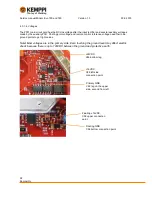
GND
IGBT 1
emitter
DC-link
IGBT 2
collector
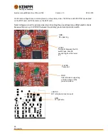
1
2
IGBT 1 emitter


