background image


Service manual Minarc Evo 150 and 180 

Version 1.3 

30.9.2015 


Kemppi Oy 


3. TECHNICAL INFORMATION 
 
3.1. Technical data 
 
Minarc Evo 150 


Summary of Contents for Minarc Evo 150

Page 1: ...Kemppi Oy SERVICE MANUAL Minarc Evo 150 180 ...

Page 2: ...n 12 4 2 1 Functions and buttons 12 4 2 2 Calibration parameters 15 4 2 3 Calibration procedure 15 4 3 Measurements and tests 16 4 3 1 Z001 Main circuit card 16 4 3 1 1 Input rectifier and PFC circuit 17 4 3 1 2 IGBT 19 4 3 1 3 Secondary rectifier 21 4 3 1 4 Voltages 22 4 3 1 5 Overheat protection 23 4 3 2 A001 control card 24 4 3 3 Cooling fan 26 4 3 4 Low voltage tests 26 4 3 5 Safety tests 26 4...

Page 3: ...hile it is turned off but it is always better to ensure this by measuring the voltage Wait at least one minute for the capacitors to become discharged Digital multimeters later DMM may give different values depending the specifications they have For example diode measuring values may vary between the DMM models In this manual Fluke 179 DMM is used This machine has all the control circuits in the p...

Page 4: ...inarc Evo can be connected to the mains supply of 230VAC 1 PFC makes possible to weld with the full power MMA 140A MMA 170 even when modern circuit breakers are used Minarc Evo control card software cannot be reprogrammed in the field Overvoltage watch is 300VAC and under voltage watch is 110VAC voltage must be increased back to 160VAC to get the inverter back to full operation after the under vol...

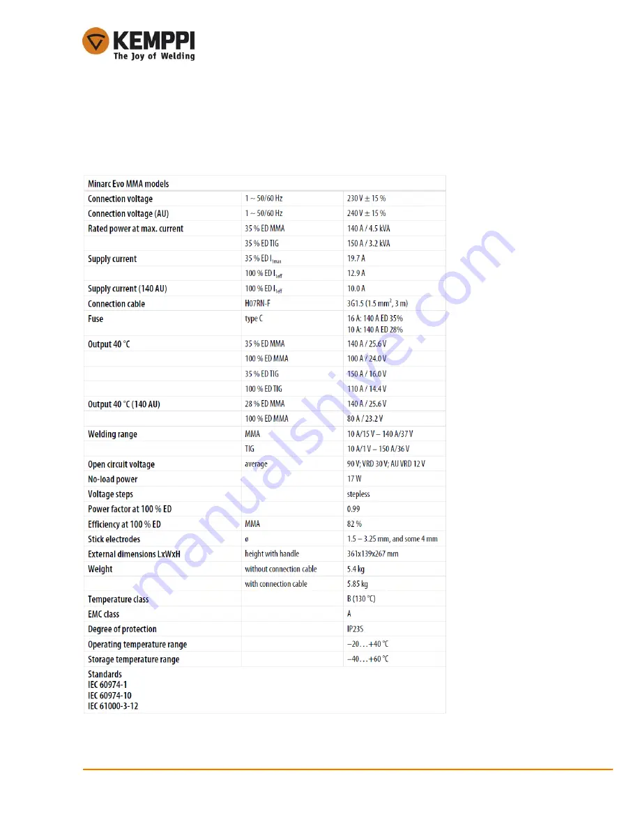
Page 5: ...Service manual Minarc Evo 150 and 180 Version 1 3 30 9 2015 3 Kemppi Oy 3 TECHNICAL INFORMATION 3 1 Technical data Minarc Evo 150 ...

Page 6: ...Service manual Minarc Evo 150 and 180 Version 1 3 30 9 2015 4 Kemppi Oy Minarc Evo 180 ...

Page 7: ...Service manual Minarc Evo 150 and 180 Version 1 3 30 9 2015 5 Kemppi Oy 3 2 Wiring diagram Latest version with better quality is available at Kemppi Channel ...

Page 8: ...mppi Oy 3 3 Construction The cooling fan is installed so that the air flows from the left side plate to Z001 card Air comes out through the front and the back plate grills Left side Front Right side Back Left side side plate removed Left side plate with cooling fan ...

Page 9: ... Version 1 3 30 9 2015 7 Kemppi Oy 3 3 1 Inner structure 1 Main switch 2 Primary heat sink 3 T001 main transformer 4 Secondary heat sink 5 Secondary choke 6 Remote control socket 7 A001 control card 8 Z001 main circuit card 1 2 3 4 5 7 6 8 ...

Page 10: ...tructure 1 2 3 4 5 6 7 9 8 1 Primary rectifier and PFC module 2 IGBT module 3 DC link capacitors 4 Main transformer 5 Secondary diodes zero side stress reduction resistor 6 Negative output connector 7 Positive output connection 8 Secondary diodes positive side 9 X9 connector to A001 card 10 PFC choke 10 ...

Page 11: ...eld programmable serial bus connection is in the primary side 2 MMA TIG selection 3 Remote ON OFF 4 Microcontroller 5 Analogic potentiometer 6 7 segment display 7 X1 connector to main circuit card flat cable 8 Overheat LED 9 VRD LED 10 Welding machine ON LED 11 TIG mode LED 12 MMA mode LED 13 Remote ON LED 1 2 3 4 5 6 7 8 9 10 11 13 12 ...

Page 12: ...d its winding has13 turns Choke slows the secondary voltage changes and works as energy storage in the long short circuits PFC choke works together with PFC circuit It has 66 turns Main circuit card itself provides the following functions DC link soft start charging and over voltage protection circuit It avoids full power connection if the primary has a short circuit or main supply voltage rises o...

Page 13: ... for the displays Machine uses primary current measuring for inverter feedback Remote control connection circuit with galvanic isolation Remote controller reading is in the A001 card Cooling fan control circuit Control signal comes from the A001 card Dual forward inverter gate driver circuit Control signal comes from the A001 card Secondary voltage monitoring in VRD mode Limit is 32VDC and if volt...

Page 14: ...at is factory programmed In these cases please contact technicalservice kemppi com 4 2 Calibration Minarc Evo must always be calibrated if an A001 control card or a Z001 main circuit card is replaced with a new one Otherwise machine maximum minimum current and or panel display may be out of range There are only two buttons and three LEDs to be used in calibration procedure See the following exampl...

Page 15: ...the following sequence Picture2 Moving between parameters Parameter 2 Current multiplier 150A Parameter 3 Display current offset min 10A 2 Press to go to the next parameter 1 Press and hold Moving to next parameter Parameter 2 Current multiplier 150A Parameter 3 Display current offset min 10A 2 Press to go to the next parameter 1 Press and hold Moving to previous parameter ...

Page 16: ...easing the parameter value affects the machine in different ways depending on the parameter Example above is for illustration only see the chapter Calibration procedure to get the step by step instructions on how to proceed Parameter 3 Display current offset min 10A Increasing the parameter value Parameter 3 Display current offset min 10A Press to increase the parameter value Press to decrease the...

Page 17: ...he factory settings recall as in the other Kemppi machines After resetting the values procedure must be carried out to ensure the machine working properly To get satisfactory and reliable calibration result welding current must be measured A current clamp meter is easiest and accurate enough for this purpose If a clamp meter is not available a standard shunt resistor and multimeter can be used In ...

Page 18: ...elect the one below 10A 6 Move to parameter 4 procedure on Picture2 Turn the potentiometer to maximum and check the panel display value Adjust parameter value procedure on Picture3 as close to 150A as possible exact value is ideal If this is not possible select the one above 150A 7 Switch off the machine disconnect the welding cable or load and connect the remote controller 8 Enter the calibration...

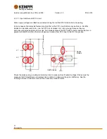
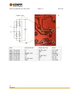
Page 19: ... circuit diodes only in two groups because they are internally connected parallel and in series Two diodes between the PFC IGBT collector and emitter are in parallel with IGBTs and the other two diodes are in series from PFC input to the DC link positive Check the diodes using a multimeter diode function to measure their threshold voltage Diodes must be measured both forward bias and reverse bias ...

Page 20: ...utput 0 2 0 7VDC Diode 3 reverse bias L1 GND No value Diode 1 reverse bias Rectifier output L1 No value Diode 3 forward bias GND L1 0 2 0 7VDC Diode 2 forward bias L2 Rectifier output 0 2 0 7VDC Diode 4 reverse bias L2 GND No value Diode 2 reverse bias Rectifier output L2 No value Diode 4 forward bias GND L2 0 2 0 7VDC GND Rectifier output L1 L2 L2 L1 1 3 2 4 ...

Page 21: ... input No value IGBT diodes forward bias GND PFC input 0 3 0 7VDC 4 3 1 2 IGBT Mains supply voltage must not be connected during the IGBT module diode measuring IGBT module can be tested by a multimeter when using the diode tester function The module holds four diodes and if IGBT is damaged in many cases these will be defective They can be measured only in pairs if main transformer primary is conn...

Page 22: ...rse bias condition to make sure they are satisfactory See following pictures and table to make all the necessary measurements Mianrc Evo 150 card IGBT 1 emitter and IGBT 2 collector are connected via main transformer it is not possible to measure all the four diodes separately without disconnecting the transformer primary Main transformer primary winding GND IGBT 1 emitter DC link IGBT 2 collector...

Page 23: ...y is disconnected IGBT 1 emitter and IGBT 2 collector connection points can be used separately to measure diodes one by one In this case the table must checked twice first using the IGBT 1 emitter point only and then the IGBT 2 collector point 4 3 1 3 Secondary rectifier Mains supply voltage must not be connected during the secondary rectifier diode measuring Use a digital multimeter to test the s...

Page 24: ...nd remote control reference voltage need their own ground points to get right values Note Most voltages are in the primary side Even touching the ground level may affect electric shock because there is up to 120VDC between the ground and protective earth 16VDC C26 left side connection point 24VDC V46 bottom leg Primary GND V62 leg on the upper side second from left Floating 16VDC C56 upper connect...

Page 25: ... Measure the resistance It should be less than 100Ω In over temperature situation PTC goes to high resistance mode 10kΩ Machine gives temperature alarm at 1 5kΩ A broken PTC has usually hundreds of kilo ohms resistance or no value at all 12VDC Test point on the right side of R22 Reference ground N3 right side third leg from top 390VDC DC link TP4 Primary GND TP5 ...

Page 26: ...chine in environment temperature 0 40 C While temperature rises resistance lowers and at 2kΩ point the inverter stops and gives overheat alert A broken NTC has usually hundreds of kilo ohms resistance no value at all or short circuit 4 3 2 A001 control card PTC common point Main transformer PTC resistor NTC common point Rectifier PFC module NTC resistor NTC common point IGBT module NTC resistor ...

Page 27: ... Note Voltages are in the primary side Even touching the ground level may affect electric shock because there is up to 120VDC between the primary ground and protective earth GND S5 upper leg 5VDC Test point between the S5 switch legs Also N3 second leg from the lower left 16VDC Test point GND C26 left side or upper leg of S5 as shown in the previous picture 24VDC R17 left side connection point GND...

Page 28: ...screwdriver while tightening any power components onto the heat sink See following sections for tightening torques 4 4 1 Rectifier PFC module and IGBT MinarcEvo 150 180 has soldered input rectifier PFC and IGBT modules and it is not possible to change them separately Only reliable way to replace the module s is to change the whole Z001 main circuit card The heat sink paste should be spread on to t...

Page 29: ...es the possibility of any contamination dirt etc getting between the components The torx fixing screws in diodes are tightened to 1 2 Nm and the resistor a smaller case than the diodes to 0 7 Nm 4 5 Final testing After the machine repair and low voltage tests it is good practice to carry out some load tests and finish with some test welds Only then is it possible to guarantee the machine is workin...

Page 30: ...chines main switch ON Adjust machine current to desired level this example uses 140A Add some load to get the inverter operate be fast in switching because arcing may exist between the connection surfaces of the switch Measure load voltage by a DMM Add or decrease load to get the desired voltage If using active load bank instead of increasing or decreasing load it is only necessary to select MMA n...

Page 31: ...Service manual Minarc Evo 150 and 180 Version 1 3 30 9 2015 29 Kemppi Oy 5 NOTES ...

Reviews: