KEMPPI PRO EVOLUTION PROCOOL 30 / 0532
© KEMPPI OY
2.5. PREPARING FOR OPERATION
Cooling liquid is injurious! Avoid also contact with skin or eyes. In case of injury,
seek for medical advice.
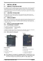
See also 2.4.2. Main parts of cooling unit.
1.
Install the cooling unit control cable into the wire feed unit.
2.
Connect the cooling water hoses with the wire feed unit, follow colour markings.
3.
Fill the reservoir with a 40 - 20 % mixture of glycol and water, or with any other suitable
antifreeze agent. The capacity of the reservoir is 3 litres.
4.
Connect the mains voltage and control connectors of the cooler unit to the corresponding
connectors on the base of the power supply. The connection can be established through the
base of the power supply when the devices are separated or through the right side of the
Procool 30 cooler by removing the right side plate.
5.
Attach the power supply on the Procool 30 cooler.
6.
Switch on the power supply.
7.
Press and hold down the test switch until the torch hoses are filled with liquid. The text
COOLER ERROR will remain on the PROMIG panel as long as the gun hoses contain air.
8.
Device is ready to weld.
3. OPERATION
3.1. COOLER OPERATION
See also 2.4.2. Main parts of cooling unit
Procool 30 Cooler operation is controlled by the microprocessor of the power supply. The cooler pump
starts to operate when the welding begins. After the welding has stopped, the pump will operate 1 to 5
minutes longer depending on the welding time. During this time the liquid will cool down to the sur-
rounding temperature. If the pump is stopped, the need for maintenance of the cooler will be reduced.
Check the tank liquid level regularly and fill in liquid, if necessary.
If the liquid flow is blocked or a hose is blocked or broken, the welding is stopped and the text
COOLER ERROR appears on the PROMIG panel.
3.2. OVERHEAT SIGNAL LAMP
The overheat signal lamp is lighting when temperature control of the machine has detected cooling
water overheat. The ventilator cools down the machine and when the lamp goes out welding can be
started again.
3.3. STORAGE
The machine must be stored in a clean and dry room. Protect the machine from rain and keep it away
from direct sunshine in places where temperature e25 °C. Check that there is free space in
front of and behind the machine for air circulation.
4. MAINTENANCE
Watch out for mains voltage when handling electric cables!
In planning product maintenance machine utilization degree and circumstances should be considered.
Careful use and preventive maintenance help to avoid unnecessary production disturbances and
breaks.
4.1. DAILY MAINTENANCE
The following maintenance opeations should be carried out daily:
•
Check water level and input flow, add liquid if needed.
•
Check cables and connections. Tighten, if necessary and replace defect parts

