www.kenall.com | P: 800-4-Kenall | F: 262-891-9701 | 10200 55th Street Kenosha, Wisconsin 53144, USA
This product complies with the Buy American Act: manufactured in the United Stateswith more than 50% of the component cost of US origin It may be covered by patents
found at www.kenall.com/patents. Content of specification sheets is subject to change; please consult www.kenall.com for current product details. ©2019 Kenall Mfg.Co.
3
INSTALLATION INSTRUCTIONS
LPS_F-5295_090418
7. Make electrical connections. Disconnect facility power to the electric power supply leads. Connect fixture leads
to power supply leads using connectors suitable for the gage and number of wires being used (not included).
MRI Fixtures:
a. Run the 24VDC supply from the EMI filter to the luminaire(s) using at least 18 AWG wires. Class 1 wiring is
required. Make sure wiring is completely enclosed in grounded conduit. Any gaps, regardless of size, must
be closed or wrapped in copper foil tape. Special attention should be paid to the wiring entry point into the
shielded space.
b. If a 0-10V dimmer is to be connected, install at this time. Dimmer must be installed outside the shielded
MRI environment with an intermediate MRI room EMI filter to the luminaires. Kenall recommends using
a Leviton® lllumaTech™ IP710 series dimmer or Grafik Eye GRX-TVI control interface. Contact Kenall for
suitability of using an alternate sink-type 0-10V dimmer.
NOTES: To prevent MRI machine interference, all DC power and dimming signal wiring must be completely shielded
within grounded conduit.
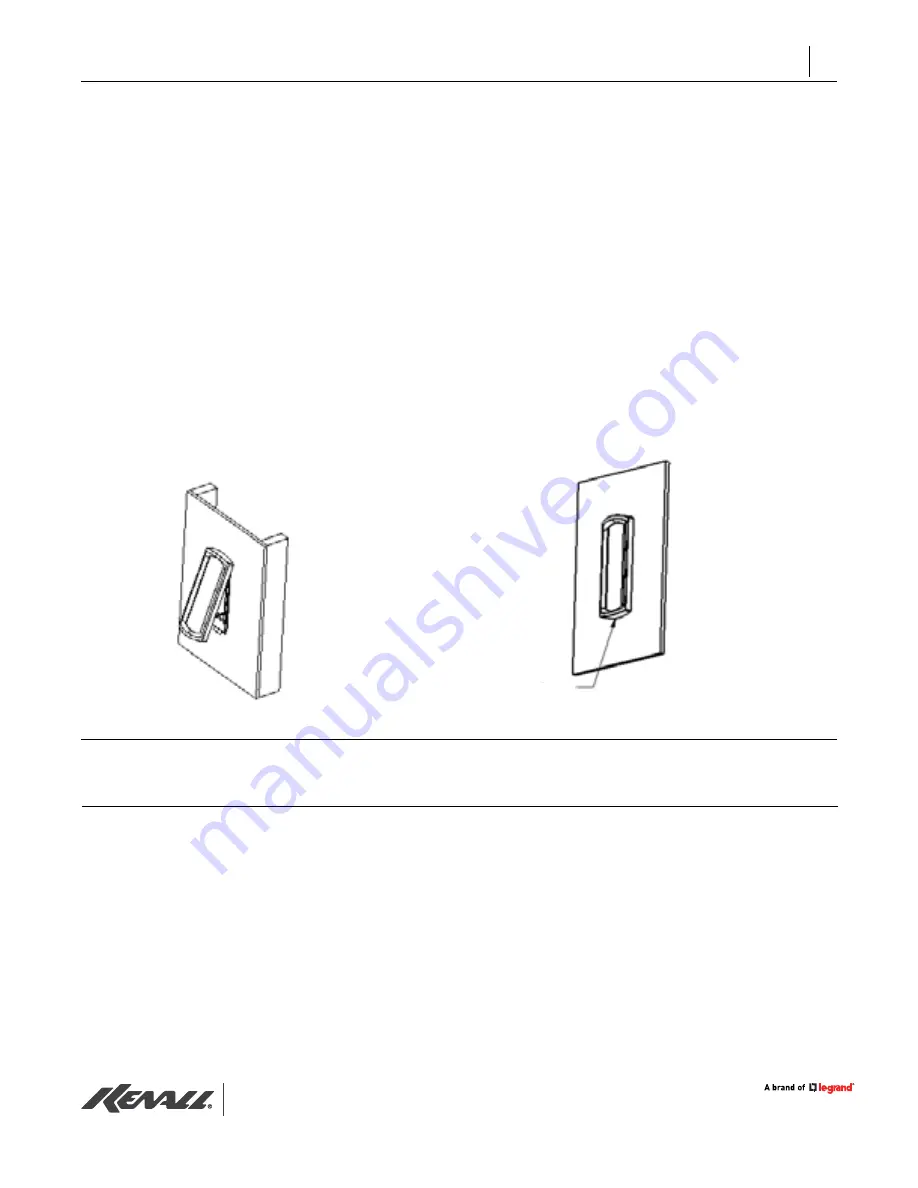
8. Install fixture. Top of housing over top of back-mounting-box's hooks.
9. Tighten screw at bottom of housing.
For technical assistance, call 1-800-4KENALL (1-800-453-6255).
CUSTOMER SERVICE
For warranty information visit www.kenall.com/Resources/Certified-Performance-Warranties
WARRANTY
Screw


