background image

Summary of Contents for 153.336931

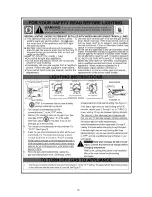
Page 1: ... CALENTADOR DE AGUA SI NO ENTIENDE LAS INSTRUCCIONES No hacer caso de esta advertencia podria originar lesiones graves o mortales P N 326709 000 0513 Sears Brands Management Corporation Hoffman Estates IL 60179 U S A www kenmore com www sears com WARNING If the information in these instructions is not followed exactly a fire or explosion may result causing property damage personal injury or death ...

Page 2: ... listed in the act This product is certified to comply with a maximum weighted average of 0 25 lead content as required in some areas IMPORTANT DEFINITIONS Qualified Technician A qualified technician must have ability equivalent to a licensed tradesman in the fields of plumbing air supply venting and gas supply including a thorough understanding of the requirements of the National Fuel Gas Code as...

Page 3: ... opposite gas Maintain required clearances to combustibles Keep ignition sources away from faucets after extended period of non use Read instruction manual before installing using or servicing water heater Improper installation and use may result in property damage Do not operate water heater if flood damaged Inspect and replace anode Install in location with drainage Fill tank with water before o...

Page 4: ...the Water Heater 15 GAS CONVERSION 15 16 GAS SUPPLY 17 18 Gas Requirements 17 Gas Piping 17 Gas Pressure 17 Gas Pressure Testing 17 LP Gas Only 18 COMBUSTION AIR SUPPLY VENTILATION 19 20 Vent Pipe System 19 Draft Hood Installation 19 Roof Jack Installation 19 Enclosure Installation 20 WATER SYSTEM PIPING 21 23 Piping Installation 21 Water Piping Pressure Test 22 Closed System Thermal Expansion 22 ...

Page 5: ...ng the Pilot Thermopile Assembly 31 32 External Inspection Cleaning of the Base Ring Filter 32 Cleaning the Combustion Chamber and Flame arrestor 33 Replacing the Manifold Burner Assembly 33 Piezoelectric Igniter System 34 Testing the Igniter System 34 Removing and Replacing the Gas Control Valve Thermostat 34 FVlR System Operational Checklist 34 TROUBLESHOOTING GUIDE 35 37 Start Up Conditions 35 ...

Page 6: ...mart purchase Your new Kenmore product is designed and manufactured for years of dependable operation But like all products it may require preventive maintenance or repair from time to time That s when having a Master Protection Agreement can save you money and aggravation The Master Protection Agreement also helps extend the life of your new product Here s what the Agreement includes Parts and la...

Page 7: ...t few pages READ THE ENTIRE MANUAL BEFORE ATTEMPTING TO INSTALL OR OPERATE THE WATER HEATER The installation must conform with these instructions and the local code authority having jurisdiction In the absence of local and state codes installations shall comply with the National Fuel Gas Code ANSI Z223 1 NFPA 54 current edition Manufactured home manufacturers The installation must conform to The M...

Page 8: ...AS Natural LP Natural LP INPUT RATE Btu hr 35 500 32 000 35 500 32 000 RECOVERY RATE GALS PER HOUR 90 F RISE 36 34 32 75 36 34 32 75 MINIMUM VENT PIPE DIA INCHES mm 3 76 OR 4 102 3 76 OR 4 102 DIAMETER INCHES mm 18 457 20 508 DIMENSIONS INCHES mm HEIGHT TO JACKET TOP 58 1473 58 25 1480 ...

Page 9: ...m DIAMETER FOR WATER HEATERS HAVING A DIAMETER 22 559 mm OR LESS BASIC TOOLS You may or may not need all these tools depending on your type of installation These tools can be purchased at your local Sears Store Pipe Wrenches 2 14 356 mm Screwdriver Tin Snips 6 1 82 m Tape or Folding Ruler Garden Hose Drill Pipe Dope or Teflon _ Tape DRILL SLOT HEAD SCREWDRIVER PHILLIPS SCREWDRIVER TIN SNIPS ROLL O...

Page 10: ... 3 12 PITCH OR LESS F G H R DO NOT CAP OR PLUG s v INSTALL THERMAL EXPANSION TANK IF WATER HEATER IS INSTALLED IN A CLOSED WATER SYSTEM ALL PIPING MATERIALS TO BE SUPPLIED BY CUSTOMERS ROOF JACK NOT FURNISHED S GAS CONTROL VALVE TH E RMOSTAT Control Temperature Knob Conversion Fitting Status Light niter 120 F Mark LOW Temperatures shown are approximates and may vary U MANIFOLD BURNER ASSEMBLY MAIN...

Page 11: ...eplaces etc Is there a furnace air handler in the same room space as the water heater If so has a return air duct system been attached that exits the room If so check for leaks on the air duct system If no air duct system is present correct immediately by contacting a local Heating Ventilation Air Conditioning Refrigeration HVAC R authorized service provider Use a fresh air supply that is free of ...

Page 12: ...5 Disconnect the vent pipe from the draft hood where it connects to the water heater In most installations the vent pipe can be lifted off after any screw or other attached devices are removed Dispose of the draft hood The new water heater has a draft hood which must be used for proper operation If you have copper piping to the water heater the two copper water pipes can be cut with a hacksaw appr...

Page 13: ...rea Site Location DO NOT install this water heater in any occupied space of the manufactured mobile home There shall be no openings between the occupied space of the manufactured mobile home and the water heater enclosure The water heater must be installed indoors and in a vertical position on a level surface Do not install in bathrooms bedrooms or any occupied room normally kept closed Locate the...

Page 14: ...ater supply to the entire home when water is detected in the drain pan Water supply shut off devices that activate based on the water pressure differential between the cold water and hot water pipes connected to the water heater Devices that wilt turn off the gas supply to a gas water heater while at the same time shutting off its water supply Securing Water Heater to Floor and Wall The water heat...

Page 15: ...ing of the tank allow air to exit by opening the nearest hot water faucet Allow water to run until a constant flow is obtained This will let air out of the water heater and the piping Check all water piping and connections for leaks Repair as needed Property Damage Hazard Avoid water heater damage Fill tank with water before operating FIGURE 10 Gas Conversion This water heater is originally shippe...

Page 16: ...s verify that NAT is marked on the exposed end of the fitting NAT must face outward toward you See Figure 12 If LP faces outward repeat step 2 Replace the cap Install the Conversion Manifold Burner Assembly 1 Check the door gasket for damage or imbedded debris prior to installation 2 Inspect the view port for damage and replace as required 3 Insert the conversion manifold burner assembly into the ...

Page 17: ...ntrol valve thermostat and the manual shut off valve This is to allow easy removal of the gas control valve thermostat 4 Turn the gas supply on and check for leaks Test all connections by brushing on an approved noncorrosive leak detection solution Bubbles will show a leak Correct any leak found MANUAL GAS SHUT OFF VALVE _ GROUND_ JOINT UNION CHECK WITH LOCAL UTILITY FOR MINIMUM HEIGHT 3 MINIMUM S...

Page 18: ... 28 26 3 4 278 190 152 130 115 105 96 90 84 79 72 64 59 55 1 520 350 285 245 215 195 180 170 160 150 130 120 110 100 1 1 4 1050 730 590 500 440 400 370 350 320 305 275 250 225 210 1 1 2 1600 1100 890 760 670 610 560 530 490 460 410 380 350 320 After the length of pipe has been determined select the pipe size which will provide the minimum cubic feet per hour required for the gas input rating of th...

Page 19: ...is ducted in from the outside see Enclosure Installation This water heater must be properly vented for the removal of exhaust gases to the outside atmosphere Correct installation of the vent pipe system is mandatory for the proper and efficient operation of this water heater and is an important factor in the life of the unit The vent pipe must be installed according to all local and state codes or...

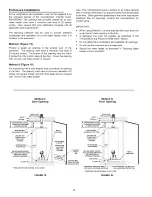
Page 20: ...ke opening with a minimum free area of 32 square inches must be provided in the skirt Other gas fired appliances in the home may require additional free air openings Consult the manufacturers for correct sizing IMPORTANT When using Method II ensure that the drain pan does not cover the air intake opening in the floor A discharge line must be installed as described in the Temperature and Pressure R...

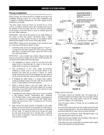
Page 21: ...ssible Know the location of this valve and how to shut off the water to the heater A temperature and pressure relief valve must be installed in the opening marked Temperature and Pressure T P Relief Valve on the water heater A discharge line must be added to the opening of the T P Relief Valve Follow the instructions under Temperature and Pressure Relief Valve After piping has been properly connec...

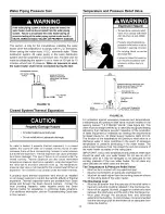
Page 22: ...additional information see the Troubleshooting Guide later in this manual Explosion Hazard Temperature pressure relief valve must comply with ANSI Z21 22 CSA 4 4 and ASME code Properly sized temperature pressure relief valve must be installed in opening provided Do not plug block or cap the discharge line Failure to follow this warning can result in excessive tank pressure serious injury or death ...

Page 23: ...and tape must not block the discharge opening or hinder access to the manual relief lever Figure 21 Ensure a discharge pipe is installed into the T P valve discharge opening per the instructions in this manual 4 Locate the hot water outlet cold water inlet pipes to the water heater 5 Locate the slit running the length of a section of pipe insulation 6 Spread the slit open and slip the insulation o...

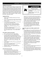
Page 24: ...ximately 120 F 6 Replace the outer door If the Pilot Does Not Light 1 Wait 10 minutes before another lighting attempt If the pilot does not light the Igniter may not be sparking or the unit may not be getting gas or for a new installation there may still be air in the gas line Each time you click the igniter button you should be able to see the spark by looking through the view port See 2 Figure 2...

Page 25: ...1 _STOP It is imperativethat you read all safety _warnings before lighting the pilot 2 Turn the gascontrol temperatureknob counterclockwise_to the OFF setting 3 Waitten 10 minutesto clear out any gas If you then smell gas STOP Follow B in the safety label If you do not smell gas go to the nextstep 4 Turn the gascontrol temperatureknob clockwiseCto PILOT See Figure B 5 Press the gas control tempera...

Page 26: ... 16 7 C higher or lower at the point of use such as bathtubs showers sink etc HOTTER WATER CAN SCALD Water heaters are intended to produce hot water Water heated to a temperature which wilt satisfy space heating clothes washing dish washing and other sanitizing needs can scald and permanently injure you upon contact Some people are more likely to be permanently injured by hot water than others The...

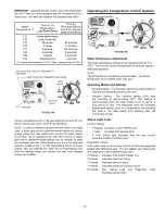
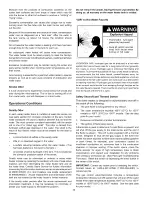
Page 27: ...sses and prevent the tank from freezing during cold weather Operating the Temperature Control System C LOW FIGURE 24B Water Temperature Adjustment The water temperature setting can be adjusted from 55 F to 155 F Turn the Gas Control Temperature Knob to the desired setting temperature NOTE The temperatures indicated are approximates The actual temperature of the heated water may vary Operating Mode...

Page 28: ... health risk or asphyxiation Chemical vapor corrosion of the flue and vent system may occur if air for combustion contains certain chemical vapors Spray can propellants cleaning solvents refrigerator and air conditioner refrigerants swimming pool chemicals calcium and sodium chloride waxes bleach and process chemicals are typical compounds which are potentially corrosive If when inspecting the ven...

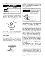
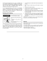
Page 29: ...e they could catch on fire Anode Rod Inspection Property Damage Hazard Avoid water heater damage Inspection and replacement of anode rod required The anode rod is used to protect the tank from corrosion Most hot water tanks are equipped with an anode rod The submerged rod deteriorates to protect the tank Instead of corroding the tank water ions attack and eat away the anode rod This does not affec...

Page 30: ...d be drained if being shut down during freezing temperatures To drain the tank perform the following steps 1 Turn off the gas to the water heater at the manual gas shut off valve 2 Open a nearby hot water faucet until the water is no longer hot 3 Close the cold water inlet valve 4 Connect a hose to the drain valve and terminate it to an adequate drain or external to the building 5 Open the water h...

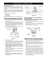
Page 31: ...lot tube 8 Remove the screws 1 4 nut driver securing the manifold burner assembly to the combustion chamber See Figure 29 9 Carefully remove the manifold burner assembly from the combustion chamber BE SURE NOT TO DAMAGE ANY INTERNAL PARTS GAS CONTROL VALVE THERMOSTAT THERMOPILE AND SWITCH WIRE GAS CONTROL _ _ CONNECTIONS TEMPERATU RE KNOB _ _ PIEZO IGNITER BUTTO PILOT TUBE ___1i i I _ _MANIFOLD TU...

Page 32: ...bend the new pilot tube to match the bend of the manifold tube NOTE When bending DO NOT crimp or crease the pilot tube 11 Before you proceed to the next step install the new brass ferrule nut in the gas control valve thermostat s pilot tube opening HAND TIGHT ONLY 12 Install the manifold burner assembly Refer to the Replacing the Manifold Burner Assembly section for instructions IGNITER WIRE PASSE...

Page 33: ...ve thermostat Figure 28 Do not cross thread or apply any thread sealant to the fittings IMPORTANT If you were supplied with a new ferrule nut in a parts kit follow these steps to connect the pilot tube 1 Install the ferrule nut into the gas valve at the pilot tube location hand tight only 2 Insert the pilot tube into the ferrule nut until the tube bottoms out then tighten the nut with a 7 16 wrenc...

Page 34: ... control valve thermostat Figure 28 5 Refer to Gas Piping Figure 2 and disconnect the ground joint union in the gas piping Disconnect the remaining pipe from the gas control valve thermostat 6 To remove the gas control valve thermostat thread a 4 section of gas pipe into the inlet and use it to turn the gas control valve thermostat counterclockwise Do not use a pipe wrench or equivalent to grip bo...

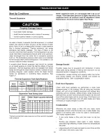
Page 35: ...G I VALVE WITH _ SHUT OFF VALVE IN FIGURE 37 Strange Sounds Possible noises due to expansion and contraction of some metal parts during periods of heat up and cool down do not represent harmful or dangerous conditions Condensation causes sizzling and popping within the burner area during heating and cooling periods and should be considered normal See Condensation section Model Number 153 331021 15...

Page 36: ...mited warranty If the smelly water persists after the anode replacement and chlorination treatment it may be necessary to chlorinate or aerate your water supply to eliminate the problem Do not remove the anode leaving the tank unprotected By doing so all warranty on the water heater tank is voided AIR In Hot Water Faucets Explosion Hazard Flammable hydrogen gases may be present Keep all ignition s...

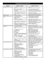
Page 37: ...nsation may be seen on pipes in humid weather or pipe connections may be leaking C The anode rod fitting may be leaking D Small amounts of water from temperature pressure relief valve may be due to thermal expansion or high water pressure in your area E The temperature pressure relief valve may be leaking at the tank fitting F Water from a drain valve may be due to the valve being slightly opened ...

Page 38: ...or firmly in socket 5 Bleed the air from the gas line 6 Check with gas utility company 7 Check with gas utility company 8 Notify utility install dirt trap in gas line 9 Locate source and correct HIGH OPERATION COSTS INSUFFICIENT HOT WATER 10 G as controt valve thermostat temperature limit was exceeded Status light will blink 4 flashes 11 Pilot line or orifice clogged 12 Non functioning thermopile ...

Page 39: ...3 4 5 6 7 8 9 SMOKING AND CARBON FORMATION SOOTING 1 2 3 4 5 6 7 8 9 Replace gas control valve thermostat Provide ventilation to water heater Check flue way flue baffle and burner Clean locate source and correct Provide fresh air ventilation Clean filter See External Inspection Cleaning of the Base Ring Filter section Clean filter See Cleaning the Combustion Chamber and Flame Arrestor section Prov...

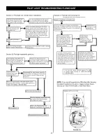
Page 40: ... MY HOME 1 800 469 4663 I YES NO l Set to desired temperature I Go to section C J Does the diagnostic status light on the gas control valve thermostat give I I a two flash error code _ I YES Refer to the Replacing the Pilot I Assemby nstructons n the manua J i I Reassemble and restore to service I Section C Pilot light wilt not remain lit Complete this section after completing Section B JCheck for...

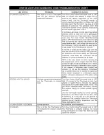
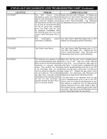
Page 41: ...t is visible and the Status Light does not blink after 90 seconds of continuous Pilot operation the Pilot flame may not be heating the Thermopite sufficiently weak Pilot the Thermopite may be defective or wiring connectors may be loose NOTE If the water heater has been operating but has stopped and wilt not re light check the flame arrestor for signs of high temperature blue or black discoloration...

Page 42: ...hermostat knob to OFF Turn Main Gas Supply OFF Replace the Gas Control Valve Thermostat See Removing and Replacing the Gas Control Valve Thermostat Turn Gas Control Valve Thermostat knob to OFF Replace the temperature sensor thermistor Turn Gas Control Valve Thermostat knob to OFF Turn Main Gas Supply OFF Replace the Gas Control Valve Thermostat See Removing and Replacing the Gas Control Valve The...

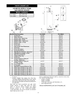
Page 43: ...1 9001886 9001886 186056 052 9006700 9006647 9006647 9000058 9000058 9008101 9008101 9008232 9008233 9006141 9006141 326709 000 326709 000 9008544 9008707 9008545 9008546 9006388 9006388 9003719 9003719 9006648 9006648 9007876 9007876 9007877 9007877 9000728 9000728 9007872 9007872 9006449 9006449 9002964005 9002964005 9002965005 9002965005 9002966005 9002966005 9002967005 9002967005 9007941005 90...

Page 44: ... items like vacuums lawn equipment and electronics call anytime for the location of your nearest Sears Parts Repair Service Center 1 800 488 1222 U S A 1 800 469 4663 Canada www sears com www sears ca To purchase a protection agreement on a product serviced by Sears 1 800 827 6655 U S A 1 800 361 6665 Canada Para pedir servicio de reparaci6n a domicilio y para ordenar piezas 1 888 SU HOGAR 1 888 7...

Reviews: