background image

Summary of Contents for 154.330040

Page 1: ...E WATER HEATER OWNER RETAIN THESE INSTRUCTIONS AND WARRANTY FOR FUTURE REFERENCE RETAIN THE ORIGINAL RECEIPT AS PROOF OF PURCHASE WARNING If the information in these instructions is not followed exactly a fire or explosion may result causing property damage personal injury or death m Do not store or use gasoline or other flammable vapors and liquids in the vicinity of this or any other appliance W...

Page 2: ... birth defects or other reproductive harm This appliance can cause low level exposure to some of the substances included in the Act IMPORTANT DEFINITIONS Qualified Technician A qualified technician must have ability equivalent to a licensed tradesman in the fields of plumbing air supply venting and gas supply including a thorough understanding of the requirements of the National Fuel Gas Code as i...

Page 3: ...the warranty Always check the water temperature before entering a shower or bath Safety Features Overheat The appliance will automatically shut down when the appliance exceeds a predetermined temperature Flame Failure The appliance will automatically shut down if the burner flame is extinguished Power Failure The appliance will cut off the gas if it loses electrical power Power Surge Fuse A glass ...

Page 4: ...High Altitude Installations 20 Connecting Multiple Water Heaters 20 Temperature Controller Installation 21 Location 21 Configurations 21 Cable Lengths And Size 21 Mounting The Controller 21 Description of Operation 22 Operating Instructions 22 Sequence of Operation 22 Features Available on Temperature Controllers 22 Temperature Adjustment 23 Temperature Options without a Temperature Controller 24 ...

Page 5: ...ime That s when having a Master Protection Agreement can save you money and aggravation The Master Protection Agreement also helps extend the life of your new product Here s what the Agreement includes Parts and labor needed to help keep products operating properly under normal use not just defects Our coverage goes well beyond the product warranty No deductibles no functional failure excluded fro...

Page 6: ...erymarch Park Quincy MA 02269 If after reading this manual you have any questions or do not understand any portion of the instructions call the Sears Service Center Carefully plan the place where you are going to put the water heater Correct combustion vent action and vent pipe installation are very important in preventing death from possible carbon monoxide poisoning and fires Examine the locatio...

Page 7: ...5 inch W C Type of Appliance Direct Vent Temperature controlled continuous flow gas hot water system Operation With Or Without Temperature Controls Mounted In Kitchen Bathroom Etc Approved Gas Type Natural Gas Or Propane Ensure Unit Matches Gas Type It s Being Installed On Connections Gas Supply 3 4 Mnpt Cold Water Inlet 3 4 Mnpt Hot Water Outlet 3 4 Ignition System Direct Electronic Ignition Elec...

Page 8: ...er 4 3 110 4 3 110 G Cold Water Inlet from wall 3 0 76 3 0 76 H Cold Water Inlet from center 1 1 27 1 1 27 I Gas Connection from wall 4 1 104 4 1 104 J Gas Connection from center 3 5 89 3 5 89 From base to gas connection 1 6 40 1 6 40 K From base to cold connection 2 0 50 2 0 50 From base to hot connection 1 6 41 1 6 41 This is the minimum dimension from the wall The wall bracket is adjustable to ...

Page 9: ...o 20 d 15 09 09 n 10 305 505 i 4 6 8 10 12 100 9O 8O 70 m d 1 6O 50 o _J 4O 30 2O a_ 10 Water Flow gpm Outlet Flow Data 9 0 8 0 7 0 E 6 0 c_ o v 5 0 0 ii 4 0 a o 2 0 1 0 0 0 0 25 50 75 100 delta T Temperature Rise F 125 150 305 505 Outdoor Manual 9 ...

Page 10: ...should be located in an area where water leakage of the unit or connections will not result in damage to the area adjacent to the appliance or to lower floors of the structure When such locations cannot be avoided it is recommended that a suitable metal drain pan adequately drained be installed under the appliance The pan must not restrict combustion air flow The flow of combustion and ventilation...

Page 11: ...ocated on the Technical Sheet attached to the inside of the front cover PCB i 120vAcco EcT e o22 RES _ liGROUN _ SW TCH Figure 3 A manual gas control valve must be placed in the gas supply line to the water heater A union can be used on the connection above the shut off valve for the future servicing or disconnection of the unit Check the type of gas and the gas inlet pressure before connecting th...

Page 12: ...iances at the location require 75 000 BTU HR Therefore the cubic feet per hour 199 000 75 000 1020 268 6 FTS HR If the pipe length is 100 ft then the 1 1 inch pipe size capable of supplying 304 FT3 HR of natural gas will be adequate TABLE 2 Pipe Sizing Table Natural Gas cubic feet per hour Schedule 40 Metallic Pipe Inlet Pressure less than 2 psi 55 inches W C Pressure Drop 0 3 inches W C Specific ...

Page 13: ...r supply system Contact the water supplier or local plumbing inspector on how to correct this situation Do not plug the relief valve Neither this water heater nor the American National Standard ANSI Z21 10 3 Canadian Standard CSA 4 3 requires a combination temperature and pressure relief valve for this appliance However local codes may require a combination temperature and pressure relief valve Fr...

Page 14: ...lenoid Valve Supply Line Route to Floor Drain i 14 3 4 Ball Valve 3 4 Union Check Valve Pressure Relief Valve KEY _ Pressure Regulator Circulating Pump I _ Boiler Drain Valve _ Solenoid Valve This is not an engineered drawing It is intended only as a guide and not as a replacement for professionally engineered project drawings This drawing is not intended to describe a complete system It is up to ...

Page 15: ...mp I _ Boiler Drain Valve _ Solenoid Valve This is not an engineered drawing It is intended only as a guide and not as a replacement for professionally engineered project drawings This drawing is not intended to describe a complete system It is up to the contractor engineer to determine the necessary components and configuration of the particular system being installed This drawing does not imply ...

Page 16: ...alve 3 4 Gas Connection _ _s Supply Minimum 3 4 Cold Water sUpprLV Line Tank Water Heater to be Sized for Heat Loss of Circulation Loop ___ Electreia_WaterI 1 Building Supply Ux u n Expansion Tank KEY I _ 3 4 Ball Valve S Pressure Regulator Z 3 4 Union _ Circulating Pump CheckValve _ Boiler Drain Valve Pressure Relief Valve D_ Solenoid Valve 16 This is not an engineered drawing It is intended only...

Page 17: ... water sandwich effect caused by frequent On Off operation Building Fixture Outlets _ Equipment List QTY Water Heaters 1 Plumbing Installation 1 Kit Optional 314 Fittings Include 2 Unions 2 Ball Valves 2 Drain Valves and I Pressure Relief Valve 3 4 Gas Connection Gas Supply Minimum 3 4 ColdWaterSupply Une Expansion Tank I 3 4 Ball Valve 3 4 Union Check Valve Z_ Pressure Relief Valve KEY _ Pressure...

Page 18: ... to service regulator vent outlet Clearance to nonmechanical air supply inlet to building or the combustion air inlet to any other appliance Clearance to a mechanical air supply inlet K L Clearance above paved sidewalk or paved driveway located on public property O M Clearance under veranda porch deck or balcony Q 12 inches 30 cm 3 feet 91 cm above if within 10 feet 3 m horizontally A vent shall n...

Page 19: ...nces Avoid termination locations near a dryer vent Avoid termination locations near commercial cooking exhaust ventilated or unventilated soffit or eve vent or to a deck or porch 50 mm between water heater terminals at same level CORNER Figure 8 305 505 Outdoor Manual 19 ...

Page 20: ... allow them to function as one hot water source The Multi Unit connection kit includes a PC board and one Multi Unit connection cable Refer to the instructions that come with the accessory for complete installation information Guidelines Do not install both the 2 Unit connection cable and the Multi Unit connection kit because they are not designed to operate together Water heaters should be instal...

Page 21: ...ller to Water Heater 1 328 ft 100 m 2 164 ft 50 m 3 or 4 65 ft 20 m Do not attempt to connect the temperature controllers with the power on There is 120 volt potential next to the temperature controller connections inside the unit Do not connect the temperature controller to the 120VAC terminals provided for the optional solenoid drain valves All service and wiring should be performed by a registe...

Page 22: ...urges combustion chamber Spark igniter begins sparking Gas control valve opens to minimum fire rate Flame rod proves ignition Spark igniter stops sparking 3 Normal Operation Electronic control board monitors flame rod fan motor frequency outlet water temperature controller temperature set point and water flow rate Gas control valve modulates gas input to required firing rate Combustion fan speed i...

Page 23: ...er heater Never allow small children to use a hot water tap or to draw their own bath water Never leave a child or handicapped person unattended in a bathtub or shower The thermostat on the water heater has been factory set at 120 F to reduce the risk of scald injury It is adjustable and can be reset to the desired temperature setting Some states have a requirement for a lower setting If you need ...

Page 24: ...a time The available temperatures for a given model are provided below Table 8 Model Temperature Settings Available F 305 Series 98 100 102 104 106 108 110 115 120 125 130 135 140 505 Series 98 100 102 104 106 108 110 115 120 125 130 135 140 Temp in Celsius 37 38 39 40 41 42 43 46 49 52 54 57 60 Re setting the Maximum Temperature Temperature settings from 125 140 F 52 60 C are available by setting...

Page 25: ...d to replace any part of the control system and any gas control which has been under water OPERATING INSTRUCTIONS 1 STOP Read the safety information above 2 Set the thermostat to lowest setting 3 Turn off all electric power to the appliance using the ON OFF button This appliance is equipped with an ignition device which automatically lights the burner Do not try to light the burner by hand Locate ...

Page 26: ...or blockages or damage Motors Motors are permanently lubricated and do not need periodic lubrication Keep fan and motor free of dust and dirt by cleaning annually Temperature Controller Use a soft damp cloth to clean the temperature controller Do not use solvents Lime Scale Build up If you receive Error Code LC refer to the procedure Flushing the Heat Exchanger Refer to the section on Water Qualit...

Page 27: ...ter and or regulator is sized properly Bleed all air from gas lines Verify dip switches are set properly Ensure appliance is properly grounded Disconnect all 2 Unit or Multi Unit connections to isolate the problem Ensure igniter is operational Check igniter wiring harness for damage Check gas solenoid valves for open or short circuits Remove burner cover and ensure all burners are properly seated ...

Page 28: ...id valve wiring harness for loose or damaged terminals Measure resistance of valve coil 52 Modulating Solenoid Valve Signal Abnormal 61 Combustion Fan Failure Ensure fan will turn freely Check wiring harness to motor for damaged and or loose connections Measure resistance of motor winding 65 Water Flow Control Fault If blank screen is present on remote control then the flow control has shorted Unp...

Page 29: ...e fan is designed to continue running for a short time after the flow of water stops This is to ensure constant water temperatures during rapid starting and stopping as well as exhausting any residual gas flue products from the unit Accessing Operating Information To display the most recent error codes press and hold the On Off button for 2 seconds While holding the On Off button press the button ...

Page 30: ...on the hot water and cold water lines Operate the pump and allow the cleaning solution to circulate through the water heater for at least 45 minutes Turn off the pump a Rinse the cleaning solution from the water heater as follows a Remove the free end of the drain hose H3 from the pail b Close service valve V2 and open shutoff valve V4 Do not open shutoff valve V3 c Allow water to flow through the...

Page 31: ...RCUiT WATER FLOW Q CON_L DEVtCE _ WATER FLOW CON TIROL DEVI CE CIRCUIT r BY PASS FLOW I CONTROL DEVICE I BY PASS SERVO MODEL ONLY DRMNG CIRCUIT DRIVING CIRCUIT T GND OUTGOING WATER _ THERMISTOR HEAT EXCHANGER r_ THERMISTOR _I _T_ _TTU RE I I1_ THERMISTOR L INDOOR MODEL ONLY MODULATING SOLENOID VALVE COMBUSTION FAN FLAME ROD Figure 15 305 505 Outdoor Manual 31 ...

Page 32: ... of the water heater Note Use the 305 Parts List for model numbers 154 330040 and 154 330050 Use the 505 parts List for model numbers 154 330080 and 154 330090 Kenmore Tankless Water Heater Accessories Part Number Description 701022 001 Standard Controller A maximum of 4 temperature controllers can be installed for a water heater or bank of water heaters for convenient temperature adjustment 90064...

Page 33: ...305 505 Outdoor Manual 33 ...

Page 34: ...34 305 505 Outdoor Manual ...

Page 35: ...305 505 Outdoor Manual 35 ...
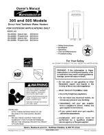
Page 36: ...ww sears com www sears ca Our Hom e iiiiiiiii For repair of carry in items like vacuums lawn equipment and electronics call anytime for the location of your nearest Sears Par epair Service Cen er iiiiiiiii 1 800 488 1222 U S A 1 800 469 4663 Canada iiiiiiiii w ear con w ears ca To purchase a protection agreement on a product serviced by Sears 1 800 827 6655 U S A 1 800 361 6665 Canada Para pedir s...

Reviews: