


6
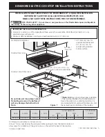
KENMORE ELECTRIC COOKTOP INSTALLATION INSTRUCTIONS
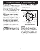
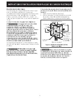
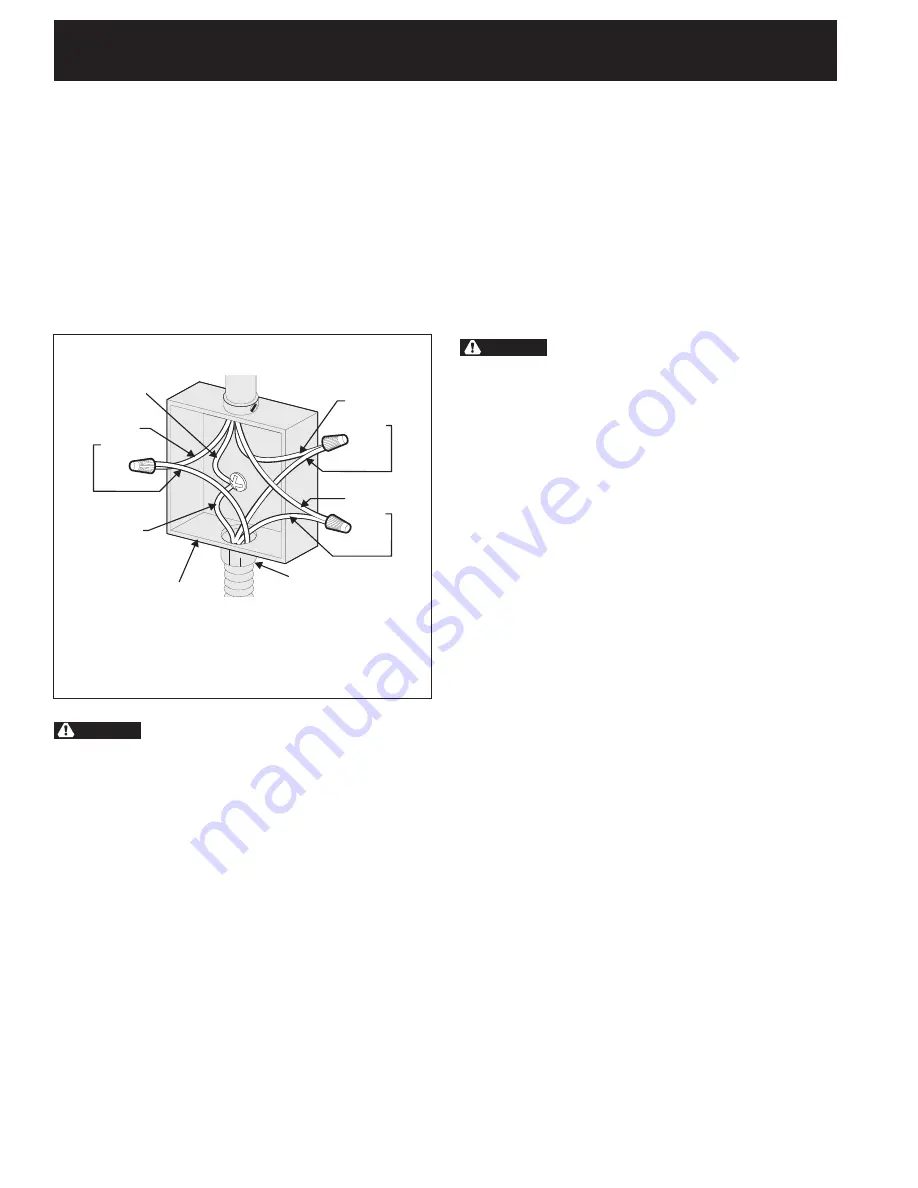
If cooktop is used in a new branch circuit
installation (1996 NEC), mobile home, recreational
vehicle, or where local codes DO NOT permit
grounding through the neutral (white) wire (see
figure 5):
1. Disconnect the power supply.
2. Separate the green (or bare copper) and white
appliance cable wires.
3. In the circuit breaker, fuse box or junction box:
connect appliance and power supply cable wires as
shown in figure 5.
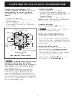
Figure 5
4-WIRE GROUNDED JUNCTION BOX
Cable from Power Supply
Junction Box
Cable from appliance
White
Wires
Black
Wires
Red
Wires
Ground Wire
Ground Wire
(Bare or Green
Wire)
U.L.-Listed Conduit
Connector (or CSA listed)
WARNING
If connecting to a 4-wire power supply
cable electrical system, the appliance frame
connected ground wire MUST NOT be connected to
the neutral wire of the 4-wire electrical system.
NOTE TO ELECTRICIAN:
The armored cable leads
supplied with the appliance are CSA-recognized for
connection to larger gauge household wiring. The
insulation of the leads is rated at temperatures much
higher than temperature rating of household wiring. The
current carrying capacity of the conductor is governed by
the temperature rating of the insulation around the wire,
rather than the wire gauge alone.
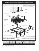
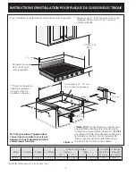
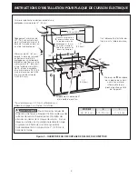
Cooktop Installation
1. Visually inspect the cooktop for damage.
2. If you are installing the optional Stainless Steel
backsplash, first fix it at the back of the cooktop using
the screws supplied with the Kit and follow the
instructions attached.
3. Set the cooktop into the countertop cutout.
NOTE:
Do not use caulking compound; cooktop should
be removable for service when needed.
Checking Operation
Refer to the
Use and Care Guide
for operation.
CAUTION
Do not touch cooktop glass or elements.
They may be hot enough to burn you.
Model and Serial Number Location
The serial plate is located under the cooktop.
When ordering parts for or making inquires about your
cooktop, always be sure to include the model and serial
numbers and a lot number or letter from the serial plate
on your cooktop.
Before You Call for Service
Read the Before You Call for Service Checklist and
operating instructions in your
Use and Care Guide
. It
may save you time and expense. The list includes
common occurrences that are not the result of defective
workmanship or materials in this appliance.
Refer to your
Use and Care Guide
for Sears service
phone numbers, or call
1-800-4-MY-HOME
®
.


