background image

Summary of Contents for 79041053100

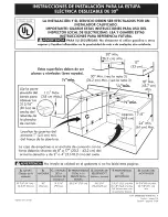
Page 1: ...top Rim Locate Cabinet Doors 1 2 5 cm Min From Cutout Opening G 30 Min _m 13 _J 30 Min see Note 3 _ t 76 2 cm Min See Note 3 18 Min _ 17 8 4 8 m F 24 Min 61 cm Mir Grounded Junction Box or Wall Outlet Be Located 8 to 17 20 3 43 2 cm From Right Cabinet and 2 to 4 5 1 10 2 cm From Floor Do not install the unit in the cabinet before reading next two pages 35 7 8 91 1 cm 36 5 8 93 cm Printed in Canada...

Page 2: ...opper 30 76 2 cm minimum clearance when the cabinet is unprotected For cutouts below 22 7 8 58 1 cm appliance will slightly show out of the cabinet Allow at least 19 1 4 48 9 cm clearance for door depth when it is open Door Open see note A Side Panel _m E E _ n_lnnl_l immlilinl IMPORTANT Cabinet and cour tertop width should match the cutout width 22 7 8 58 1 cm min 23 1 4 59 05 cm max e see Note 4...

Page 3: ...nto the cabinet Make sure the center of the unit is aligned with the center of the cabinet cut out Remove the protective channels on each side of the glass cooktop if provided The metal flange under each side of the cooktop MUST be placed over the cabinet countertop for proper unit support The glass cooktop should NOT directly touch the countertop see illustration 2 or could cause glass breakage v...

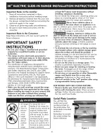
Page 4: ...e top rear edge of the range and carefully tilt it forward to make sure the range is anchored at least 90 F above room temperature without shrinking warping or dlscoloring Do not install the range over carpeting unless you place an insulating pad or sheet of 1 4 thick plywood between the range and carpeting Never leave children alone or unattended in the area where an appliance is in use As childr...

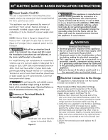
Page 5: ...A in a new branch circuit installation 1996 NEC mobile home or recreatlonal vehlcule where local code do not permit grounding through neutral white wire or in Canada remove the grounding strap from the frame and cut the other end near the neutral terminal Connect the appliance in usual manner Electrical Shock Hazard Electrical ground is required on this appliance Do not connect to the electrical s...

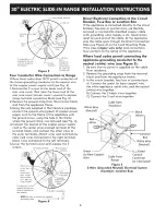
Page 6: ... Terminal Wire 1 1 8 Direct Connection Hole Punch out knockout for 1 3 8 Dia Cord Kit Hole Direct Electrical Connection to the Circuit Breaker Fuse Box or Junction Box If the appliance is connected directly to the circuit breaker fuse box or junction box use flexible armored or nonmetallic sheathed copper cable with grounding wire Supply a U L listed strain relief at each end of the cable At the a...

Page 7: ... not have cabinet storage space above the range If there is cabinet storage space above range reduce risk by installing a range hood that projects horizontally a minimum of 5 12 7 cm beyond the bottom of the cabinet Cauntertap Preparatian The cooktop sides of the range fit over the cutout edge of your countertop If you have a square finish fiat cauntertap no countertop preparation is required Cook...

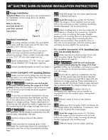
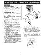
Page 8: ...eling legs Slide the range into the cutout opening and center it before leveling it Level the range see section 5 The floor the range is to be installed must be level Follow the instructions under Leveling the Range Models Equipped with Leveling Device te_coAdjust that the underside of leveling legs SO oktop is sitting on the countertop Carefully screw in refer to Leveling the range Models equippe...

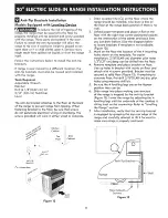
Page 9: ...urn clockwise to lower or counterclockwise to raise b To adjust the rear legs use a ratchet or a nutdriver and turn the leveling screws counterclockwise to lower or clockwise to raise 3 Check if the range is level by installing an oven rack in the center of the oven and placing a level on the rack Figure 10 4 Take 2 readings with the level placed diagonally in one direction and then the other Leve...

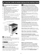
Page 10: ... element will become red Convection some models When the oven is set to CONV BAKE ROAST at 350 F 177 C the convection element cycles on and off and the convection fan turns The convection fan will stop turning when the oven door is opened during convection baking or roasting Warmer Drawer some madels Set the control knob to HI and check to see the drawer is heating When Power Connection is Complet...

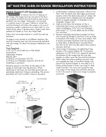
Page 11: ...ere is no wall 2 Unfold paper template and place it fiat on the floor with the right rear corner positioned exactly on the intersection of the center and back lines you just drew before Use the diagram below to locate brackets if template is not available Figure 12 3 Mark on the floor the location of the 4 mounting holes shown on the template For easier installation 3 16 0 48 cm diameter pilot hol...

Page 12: ...ere the back and sides of range will be located when installed Use the diagram below to locate brackets if template is not available Figure 14 2 Mark on the floor the location of the 4 mounting holes shown on the template For easier installation 3 16 0 5 cm diameter pilot holes 1 2 1 3 cm deep can be drilled into the floor 3 Remove template and place brackets on floor with turned up flange to the ...

Page 13: ...cocinar 1 1 2 M6x 3 8 cm M6x Localice las puertas del armario 1 2 5 cm mfn del hueco de la abertura 30 Mfn 1 76 2 cm Min 13 ___ _ 33cm _ 30 Min vea la nota 3_t 76 2 cm Mfn yea la nota 3 18 Mfr 1 4 _mj11 45 7 cm M n G 7 8 24 Mfn 61 cm Mf La caja de empalmes o el enchufe de conexi6n con la tierra debeda situarse de 8 a 17 20 3 43 2 cm del armario derecho y de 2 a 4 5 1 10 2 cm del suelo No instale l...

Page 14: ...o de 30 76 2 cm cuando el armario no est6 protegido O Para los recortados 22 menos que 7 8 eJ electrodom stico aparecerfa ligeramente en el exterior del armario O Deje par los 19 1 4 48 9 cm de espacio libre para la profundidad de la puerta cuando esta abierta Puerta abierta vea nota 5 t A Panel Lateral IMPORTANTE E ancho de la cubierta y el armario debe de set igual al ancho del corte E E PARTE D...

Page 15: ...para una unidad con un dimensi6n de 31 s j 79 5 cm Deslice la unidad hacia el gabine re Aseg0rese que la unidad es re cen rrada con el cen rro de la aber rura del gabine re Remueva la par re en pl6s rico ex rruido en cada lado de la cubier ra de vidrio Algunos modelos Es imprescindible que el reborde de metal que se encuen rra deba o de la cubier ra es re sobre la cubier ra del gabine re La cubier...

Page 16: ...terior de la cocina y inclinela hacia adelante cuidadosamente para asegurar que la cocina esta sujetada Nunca deje a los nifias solos a sin culdado en el area dande el eJectrodam_stlco et6 en usa A medida que los nihos crezcan ens6heles el usa adecuado de los electrodom6sticos Nunca deje la puerta del horno abierta cuando la cocina est6 sin supervisi6n Pisar apoyarse o sentarse en las puertas o lo...

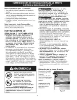
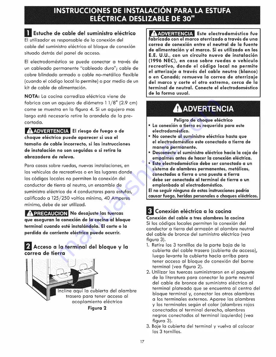
Page 17: ...alaci6n 1996 NEC en casa sabre ruedas a vehiculo recreativa dande el c6diga lacal na permite el atterizaje a tray s del cable neutro blanca a en Canada remueva la carrea de aterrizaje del marca y carte el afro extrema cerca de la termlnal de neutral Canecte el electradam_stica de la farina usual Peffgra de choque el_ctrico La canexi6n a tierra es requerida para este electradam_stica Ha canecte al ...

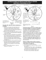
Page 18: ...elva al cotocar los 3 tornillos Atambre Rojo Alambre Necjro de ta conexi6n directa Retira la arandela pre cortada para 1 3 8 3 5 cm dia acjujero Una arazadera de releva provista debe de estar instatada a est6 ubicaci6n Hacia el 240 V recept6culo NOTA Asecjurese de quitar _ la banda de puesta a tierra provista Figura 4 Conexi6n el_ctrica cfirecta al cortacircuito a la caja de fusibles o la caja de ...

Page 19: ...Construcci6n del armario Para etiminar et riesgo e quemaduras o de fuego tratando de alcanzar algo por encima de las zonas calientes evite de colocar artfcutos sobre la cocina Si cree necesitar este espacio el riesgo puede disminuir si instala un sombrerete que proteja horizontalmente un mfnimo de 5 12 7cm sobre la base det armario Preparaci6n del mostrador Las extremidades de la cocina sobrepasan...

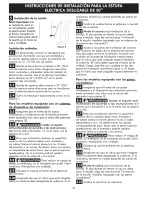
Page 20: ...cesario tevante la unidad bajando las paras de nivelaci6n _ Deslice ta unidad hacia el gabinete y central antes de nivelarta Nivele la cecina vea Nivelaci6n de la estufa El piso donde se instaia ta cocina debe estar nivelado Siga tas instrucciones nivelaci6n de la estufa modelos equipado con un sistema de dispositivo de nivelaci6n Ajuste a las patas de nivetaci6n de manera que la parte de abajo de...

Page 21: ...y dar vuelta manecitlas del reloj para bajar el nivel o ai contrario para levantar el nivel b Para ajustar las patas traseras use desarmador y dar vuelva manecillas del reloj a los tornitlos de nivetaci6n para tevantar el nivel o at contrario para bajar el nivel 3 Verifique si la cocina est6 nivelada colocando una parritla en el centro del homo y poniendo un nivel sabre esta figura 10 4 Mida dos v...

Page 22: ... 350 F 177 C los dos elementos se enciendan y se apagan alternando en un ciclo y el ventilador se pone en marcha Et ventitador de convecci6n se parar6 cuando se abre ta puerta det horno durante el cocido o el asado por convecci6n Ca i6n calentador aj_gl unos modelos Ponga la perilta de control a Hi y verifique que se est6 calentando el caj6n Despu_s de Terminar la Instalaci6n AsegOrese de que todo...

Page 23: ...osterior de la cocina 2 Desptegar el molde de papel y colocarto atisado sobre el piso con et v6rtice posterior derecho posicionado exactamente en la intersecci6n de las lineas central y posterior dibujadas anteriormente Si no se dispone de un motde usar el diagrama incluido a continuaci6n para ubicar las m6nsulas Fig 11 3 Marque en el suelo la ubicaci6n de los cuatro orificios de montaje que apare...

Page 24: ...ble la plantilla de papel y col6quela plana en ei piso con los bordes laterales y el trasero colocados exactamente donde la parte trasera y los iados de la estufa ser6n co ocados cuando sea instalada Use ei diagrama siguiente para ubicar los soportes si no se dispone de la plantiila Ver la Figura 13 2 Marque en el piso la ubicaci6n de los 4 agujeros de montaje coma se muestra en la planti la Para ...

Reviews: