background image

Summary of Contents for 79075353310

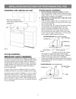
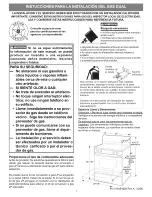
Page 1: ...anti tip device in place and engaged e Failure to follow these instructions can result in death or serious burns to children and adults ii Range leveling leg _ Anti tip S bracket To check if the anti tip bracket is installed properly use both arms to grasp the rear edge of the range back Carefully attempt to tilt range forward When properly installed the range should not tilt forward ii Refer to t...

Page 2: ...ppliance can only be installed in the State of Massachusetts by a Massa chusetts licensed plumber or gas fitter When using a flexible gas connector it must not exceed 3 feet 36 inches in length A T handle type manual gas valve must be installed in the gas supply line to this appliance Be sure your range is installed and grounded properly by a qualified installer or service technician This range mu...

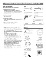
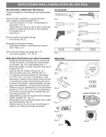
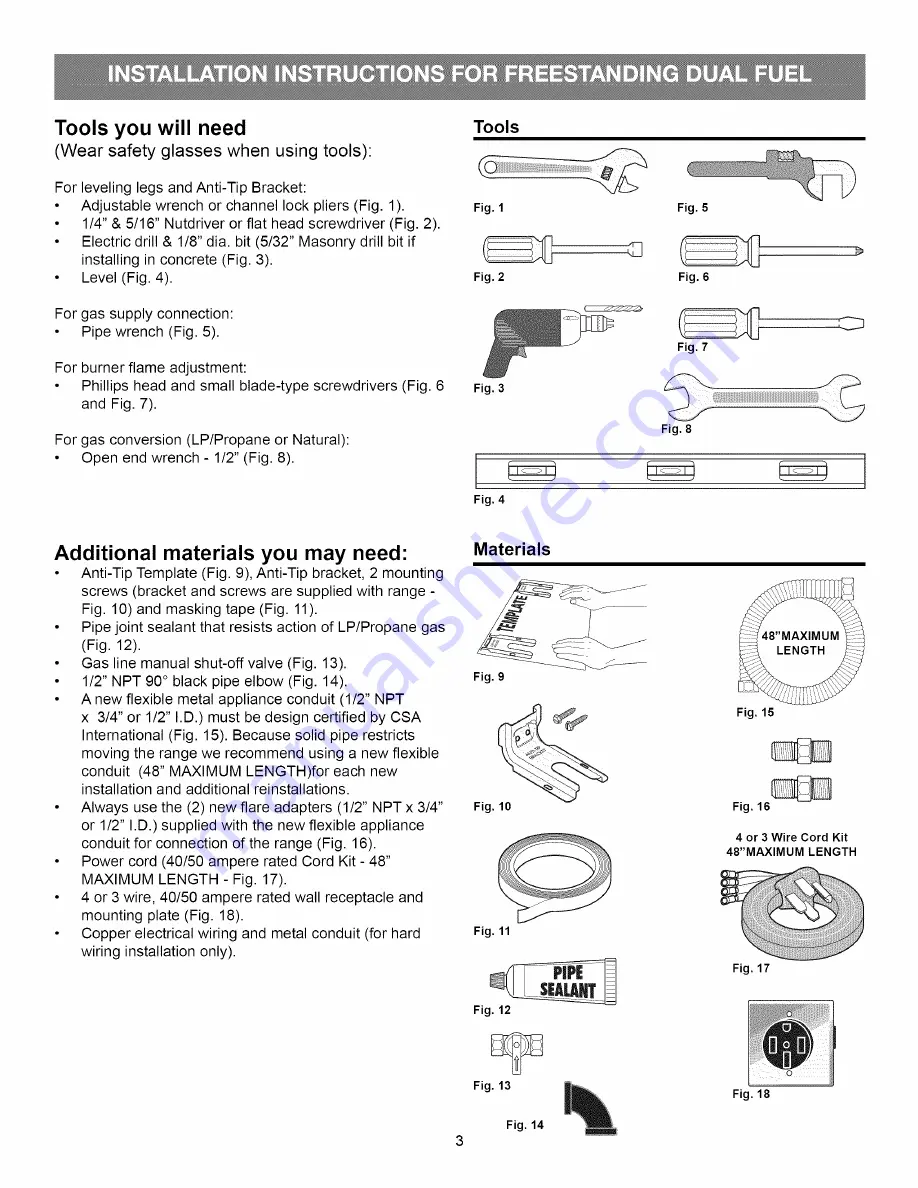
Page 3: ...pe Fig 11 Pipe joint sealant that resists action of LP Propane gas Fig 12 Gas line manual shut off valve Fig 13 1 2 NPT 90 black pipe elbow Fig 14 A new flexible metal appliance conduit 1 2 NPT x 3 4 or 1 2 I D must be design certified by CSA International Fig 15 Because solid pipe restricts moving the range we recommend using a new flexible conduit 48 MAXIMUM LENGTH for each new installation and ...

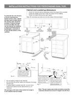
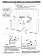
Page 4: ... Minimum on depth for cabinets either side of above ramge top range Minimum 30 Cabinet ig Back Wall Electric here Fig A 2 1 4 Back Wall Fig B Install a flush mount 240V 40 50 ampere electrical wall outlet in the shaded area Do not seal the range to side cabinets Do not pinch the power supply cord between the range and the wall If cabinet depth is greater than 25 the oven front frame must extend be...

Page 5: ...et installation 1 Place the Bracket Using the Template Bracket may be positioned on either the left or right side of the range Refer to Fig 19 Fig 20 and Fig 22 to position the bracket if template is not available 2 Mark the floor or wall where left or right side of the range will be located If rear of range is against wall or no further than 1 1 4 from wall when installed you may use the wall or ...

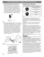
Page 6: ...ppliance must be properly installed and grounded by a qualified technician in accordance with the National Electrical Code ANSI NFPA No 70 latest edition and local electrical code requirements This appliance may be connected by means of permanent Hard Wiring or Power Supply Cord Kit When hard wiring do not leave excess wire in range compartment Excess wire in the range compartment may not allow th...

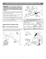
Page 7: ...minal block The rear access cover must be removed To remove loosen center screw one screw and remove access cover The terminal block will then be accessible See Fig 25 Rerno_ve Access Cover to install Power Cord Replace after installation Fig 25 Rear of Range 1 1 8 Dia 7 8 Dia Knockout Hole See Chart See Chart Mounting Plate 1 3 8 Pocket Hole for Cable See Chart Mounting Plate Fig 26 Range Connect...

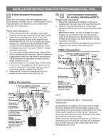
Page 8: ...elief bushing Center or white wire must always be attached to the center terminal on block Fig 29 Connect neutral white or center here Connect line 2 here OR _ 3 wire connection instructions _ for existing installations ONLY Power Cord Instructions 1 Follow the manufacturer s installation instructions supplied with the strain relief and install See Fig 28 2 Insert the end connectors for Line 1 Lin...

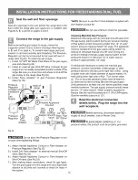
Page 9: ...d ground screw plate to release the factory installed copper ground strap from frame of the appliance Cut and discard the copper strap from the terminal block KEEP the ground screw ground plate and go to Step 4 GROUND PLATE _ A GROUND SCREW Fig 32 GROUND 4 WIRELEAD PROPER GROUND FOR 4 WIRE PERMANENT CONNECTION 4 4 Wire Permanent Connection ONLY Connect the ground wire lead Green to the frame of th...

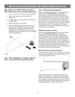
Page 10: ...oximately 1 2 psig The appliance must be isolated from the gas supply piping system by closing its individual manual shut off valve during any pressure testing of the gas supply piping system at test pressures equal to or less than 14 of water column pressure approximately 1 2 psig If it should be necessary to check the manifold gas pressure connect manometer water gauge or other pressure device t...

Page 11: ...PILLS FOOD CLEANING AGENTS ORANY OTHER MATERIAL TO ENTER THE GAS ORIFICE HOLDER OPENING Always keep the Burner Caps and Burner Heads in place whenever the surface burners are in use Check electric ignition of surface burners Operation of electric igniters should be checked after range and supply line connectors have been carefully checked for leaks and range has been connected to electric power a ...

Page 12: ...ng sure to level the range and check gas connections for leaks See anti tip instructions for proper anti tip anchoring instructions Before you call for service Refer to the Use Care Guide for cleaning instructions If removing the range is necessary for cleaning or maintenance shut off the gas supply Disconnect the gas and electrical supply If the gas or electrical supply is inaccessible lift the r...

Page 13: ...d No utilice la estufa sin el dispositivo antivuelco instalado y acoplado Sinose siguen estas instrucciones se puede provocar la muerte o quemaduras graves en niSos y adultos n T renl _dorde 0 es u 0 Para verificar si el soporte antivuelco est_ instalado correctamente sostenga el borde trasero de la parte trasera de la estufa usando ambos brazos Intente indinar la estufa hacia adelante con cuidado...

Page 14: ...cuerdo con los c6digos locales o en ausencia de ellos con el C6digo EI6ctrico Nacional ANSI NFPA No 70 Qltima edici6n cuando es instalada en los Estados Unidos Vea las lnstrucciones para la Puesta a Tierra en la p gina 20 y 21 de los Pasos de la Instalaci6n de la Estufa Antes de instalar la estufa en un rea que est6 cubierta con lin61eoo con cualquier otro revestimiento sint6tico de piso asegQrese...

Page 15: ...esto sellador de juntas resistente al gas G L P Propano Fig 12 Llave de cierre de la tuberia del gas Fig 13 Codo de tuberia negro de NPT 90 Fig 14 Un conducto nuevo para artefacto de metal flexible 1 2 NPT x 3 4 o 1 2 de D I certificado por CSA International Debido a que la tuberia s61ida restringe la movilidad de la estufa recomendamos que use un conducto nuevo flexible LARGO MAXIMO 48 para cada ...

Page 16: ...ualquier lado de la la cubierta de la estufa armarios estufa l Fig A i i_iii Ubicaciones sugeridas para la alimentacibn el_ctrica 30 Ancho de la abertura para el gabinete ParedTrasera Surqinistr0 el0ctrico aqui 2 1 4 Pared Trasera Fig B En esta area rayaka instale un tomacorriente el trico mural embutido de 240V 40 50 amperios No selle la estufa a los armarios laterals No apriete el cable el ctric...

Page 17: ... colocar el soporte si no se dispone de la plantilla 2 Marque el piso o la pared donde se colocara el lado izquierdo o derecho de la estufa Si la parte trasera de la estufa sera colocada contra la pared o a no mas de 1 1 4 de la pared cuando ya est6 instalada usted puede usar el metodo de instalaci6n en el piso o en la pared Fig 19 Para montaje en la pared Fig 19 ubique la plantilla colocando el b...

Page 18: ...ado y puesto a tierra en forma correcta por un t6cnico calificado de acuerdo con el C6digo Nacional de Electricidad ANSI NFPA No 70 Oltima edici6n y los requerimientos del c6digo local de electricidad Este artefacto debe ser conectado mediante cableado permanente o el Juego de Cable de Alimentaci6n EI6ctrica Cuando use cable no deje el exceso de cable en el compartimiento de la estufa El exceso de...

Page 19: ...es Se debe retirar la cubierta de acceso trasera Para retirar afloje el tornillo central un tornillo y retire la cubierta de acceso De este modo tendra acceso al tablero de bornes Ver Fig 25 Retire la cubierta de acceso para instalar el cable de alimentacion Vuelva a colocar la cubierta despu_s de la instalacibn Fig 25 Parte trasera de la estufa Disco removible Agujero de de 1 1 8 de diam 7 8 de d...

Page 20: ...puesta a tierra con el tornillo de tierra NOTAS Instale el buje sujetacable El alarnbre central o blanco debe eatar siernpre instalado en el borne central del tablero de berries Fig 29 O Instrucciones para conexibn trifilar para instalaciones existentes SOLAMENTE Instrucciones para el Cableado 1 Siga las instrucciones de instalaci6n del fabricante suministradas con el sujetacable e instale Ver Fig...

Page 21: ...rra de cobre del marco del electrodomestico CONSERVE el tornillo de tierra la placa de tierra y siga con el Paso 4 PLACA DE CONEXION _ ATIERRA TORNILLO DE CONEXION A TIERRA Fig 32 CABLE TERMINAL DE CONEXION A TIERRA TIERRA APROPIADA PARA _ CONEXION PERMANENTE TETRAFILAR 4 Conexi6n permanente tetrafilar SOLAMENTE Conecte el alambre terminal de puesta a tierra Verde al marco del electrodomestico usa...

Page 22: ...as hacia la estufa y use un detector de fugas liquido en todas las juntas NOTA AsegQrese de usar los 2 adaptadores abocinados suministrados con el Juego de Conducto Flexible No use una llama para verificar si hay fugas de gas Verificaci6n de la Presi6n del Gas en el Colector Desconecte la estufa y su valvula de cierre individual del sistema de tuberia del suministro de gas cuando efectQe cualquier...

Page 23: ... tapas de los quemadores y las cabezas de los quemadores en sus lugares cuando se usen los quemadores superiores iiiiiiiiiiiiiiiiiii i Verifiqueelencendidoeldctricodelos quemadores superiores Se debe revisar el funcionamiento de los encendedores electricos despues de que la estufa y los conectores de la tuberia de suministro han sido cuidadosamente revisados para verificar fugas y la estufa ha sid...

Page 24: ...a desconectar el gas y la electricidad Termine de retirar la estufa para reparaci6n y limpieza Vuelva a instalar en el orden inverso asegurandose de nivelar la estufa y revisar las conexiones del gas para verificar si hay fugas Ver en la pagina 3 de este documento las instrucciones para anclaje correcto del soporte antivuelco Antes de Hacer una Llamada de Servicio Lea la secci6n Antes de Solicitar...

Reviews: