19
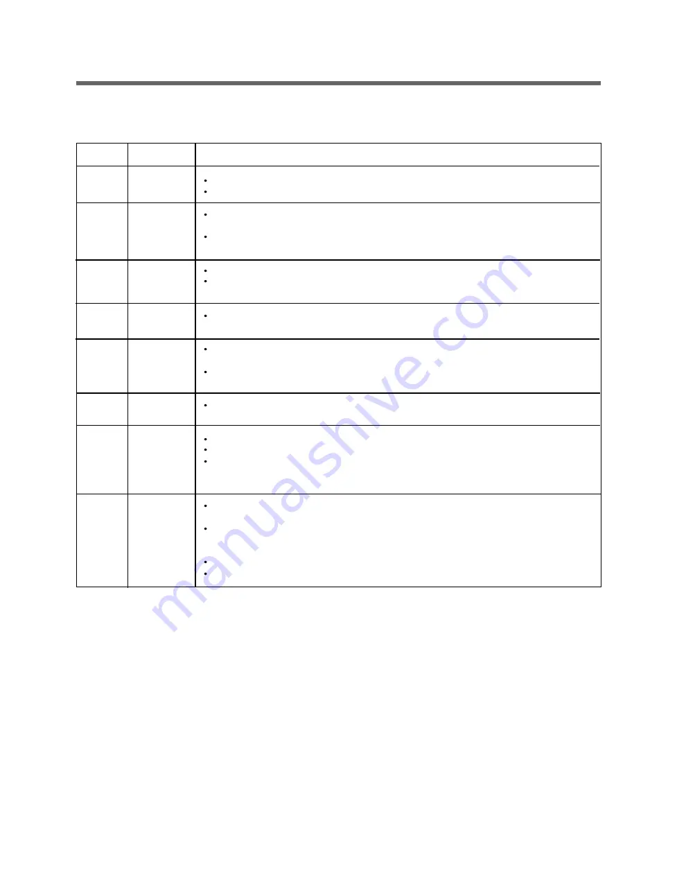
5-5. EXPLANATION OF EACH PROCESS
No.
1.
2.
3.
4.
5.
-
6.
7.
8.
9
Stay
Water
Supply
Soaking
& washing
Laundry
Heating &
washing
Washing
& heating
/ washing
Washing
Drainage
Untangling
(Sensing
eccent-
ricity)
Process
Explanation
Electrical power is supplied
Washer is ready to work and the micom is in the active mode.
After loading laundry and selecting a course and a cycle, water is
supplied and drum rotates.
When a user selects Pre-wash course, water is supplied through
pre wash valve.
To get laundry wet, drum rotates clockwise and counterclockwise.
If water amount is insufficient at this time, the Inlet valve will supply
water again.
The heater heats the water in drum to the selected water temperature
and drum rotates for washing.
When the water temperature reaches to the selected temperature, the
heating stops and only the drum rotates.
If water temperature becomes lower than selected because of
re-supplied water, the heating starts again.
Fuzzy Logic decides washing time according to the laundry load, water
temperature, and other factors.
A pump motor drains the water from the drum.
After sensing drained water amount by water level frequency, spin starts.
When a heating course is selected, stay cooling process is performed to
decrease the water temperature gradually to prevent laundry from being
damaged and for safety reasons.
It balances laundry load and senses the eccentricity of the load, to only
allow spinning without vibration
If the eccentricity is worse than the allowed level, it repeats the
disentangling process. When the repeated time is more than allowed
level, it displays UE.
If the eccentricity is good, the intermittent spin starts.
During this process, the drain pump works for drainage intermittently.
Summary of Contents for 796.4107 31 Series
Page 2: ...JULY 2012 PRINTED IN KOREA P No MFL67307945 ...
Page 12: ...5 OPERATION 13 5 1 CONTROL PANEL FEATURES ...
Page 13: ...14 ...
Page 20: ...6 TROUBLESHOOTING SUMARTY 21 ...
Page 21: ...22 ...
Page 22: ...SPIN SPEED SOIL LEVEL WASH RINSE DELAYWASH 7 TEST MODE 23 ...
Page 26: ...27 DRAIN ERROR Wash Temp DELAY WASH SPIN SPEED SOIL LEVEL ...
Page 34: ... 0 1 2 3 3 4 35 ...
Page 37: ... 9 COMPONENT TESTING INFORMATION 38 ...
Page 44: ...45 9 5 INLET VALVE ASSEMBLY ...
Page 46: ...47 9 7 THERMISTOR ASSEMBLY Circuit in the MAIN PCB Wiring Diagram ...


