41
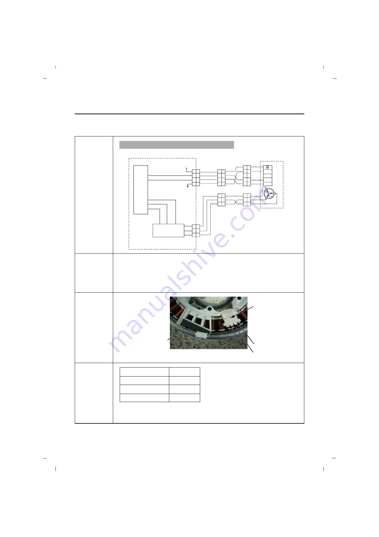
9-3. STATOR ASSEMBLY
Wiring
diagram
Circuit in the MAIN PWB / Wiring Diagram
MAIN PWB
MICOM
Ha
12V
NA1NA
WH
WH
GND
MOT
OR
Hb
Ha
RD
RD
BL
BL
GY
YL
w
w
v
u
v
u
BL
RD
RD
RD4
IPM
GY
YL
w
u
v
BL
RD
1
1 1
2
3
4
2
3
1
2
3
1
2
3
1
2
3
1
2
3
1
3
2
2
1
3
4
1
2
3
4
5
1
2
3
4
5
2
3
4
1
2
3
4
Hb
Function
Test points
(Windings)
Result
(Windings)
The Direct Drive motor can be driven from stopped to maximum speed in infinite
steps in either direction.
There are 36 poles on the stator; 12 permanent magnets spaced around the rotor.
There are no brushes to wear out. Unlike a more traditional brushless motor, the
rotor surrounds the stator rather than being attached to it.
Test Points
Result
(1) to (2)
(2) to (3)
(3) to (1)
5-15
Ω
5-15
Ω
5-15
Ω
WINDINGS
HALL SENSOR
(1)
(2)
(3)
Summary of Contents for 796.4107 31 Series
Page 2: ...JULY 2012 PRINTED IN KOREA P No MFL67307945 ...
Page 12: ...5 OPERATION 13 5 1 CONTROL PANEL FEATURES ...
Page 13: ...14 ...
Page 20: ...6 TROUBLESHOOTING SUMARTY 21 ...
Page 21: ...22 ...
Page 22: ...SPIN SPEED SOIL LEVEL WASH RINSE DELAYWASH 7 TEST MODE 23 ...
Page 26: ...27 DRAIN ERROR Wash Temp DELAY WASH SPIN SPEED SOIL LEVEL ...
Page 34: ... 0 1 2 3 3 4 35 ...
Page 37: ... 9 COMPONENT TESTING INFORMATION 38 ...
Page 44: ...45 9 5 INLET VALVE ASSEMBLY ...
Page 46: ...47 9 7 THERMISTOR ASSEMBLY Circuit in the MAIN PCB Wiring Diagram ...


