49
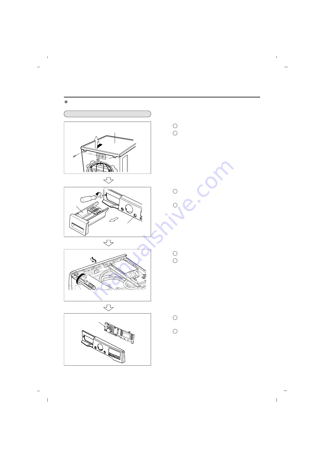
Be sure to unplug the machine before disassembling and repairing the parts.
CONTROL PANEL
1
Unscrew 2 screws on the back of the top plate.
2
Pull the top plate backward and upward as
shown.
3
Disconnect the Display PWB assembly
connector from the cabling.
4
Pull out the drawer and unscrew 2 screws.
5
Remove one screw.
6
Lift the side the control panel assembly and
pull it out.
7
Unscrew the 8 screws from the control panel
assembly.
8
Disassemble the display PWB assembly.
TOP PLATE ASSEMBLY
CONTROL PANEL ASSEMBLY
DRAWER
CONTROL PANEL ASSEMBLY
DISPLAY PWB ASSEMBLY
10. DISASSEMBLY INSTRUCTIONS
Summary of Contents for 796.4107 31 Series
Page 2: ...JULY 2012 PRINTED IN KOREA P No MFL67307945 ...
Page 12: ...5 OPERATION 13 5 1 CONTROL PANEL FEATURES ...
Page 13: ...14 ...
Page 20: ...6 TROUBLESHOOTING SUMARTY 21 ...
Page 21: ...22 ...
Page 22: ...SPIN SPEED SOIL LEVEL WASH RINSE DELAYWASH 7 TEST MODE 23 ...
Page 26: ...27 DRAIN ERROR Wash Temp DELAY WASH SPIN SPEED SOIL LEVEL ...
Page 34: ... 0 1 2 3 3 4 35 ...
Page 37: ... 9 COMPONENT TESTING INFORMATION 38 ...
Page 44: ...45 9 5 INLET VALVE ASSEMBLY ...
Page 46: ...47 9 7 THERMISTOR ASSEMBLY Circuit in the MAIN PCB Wiring Diagram ...


