57
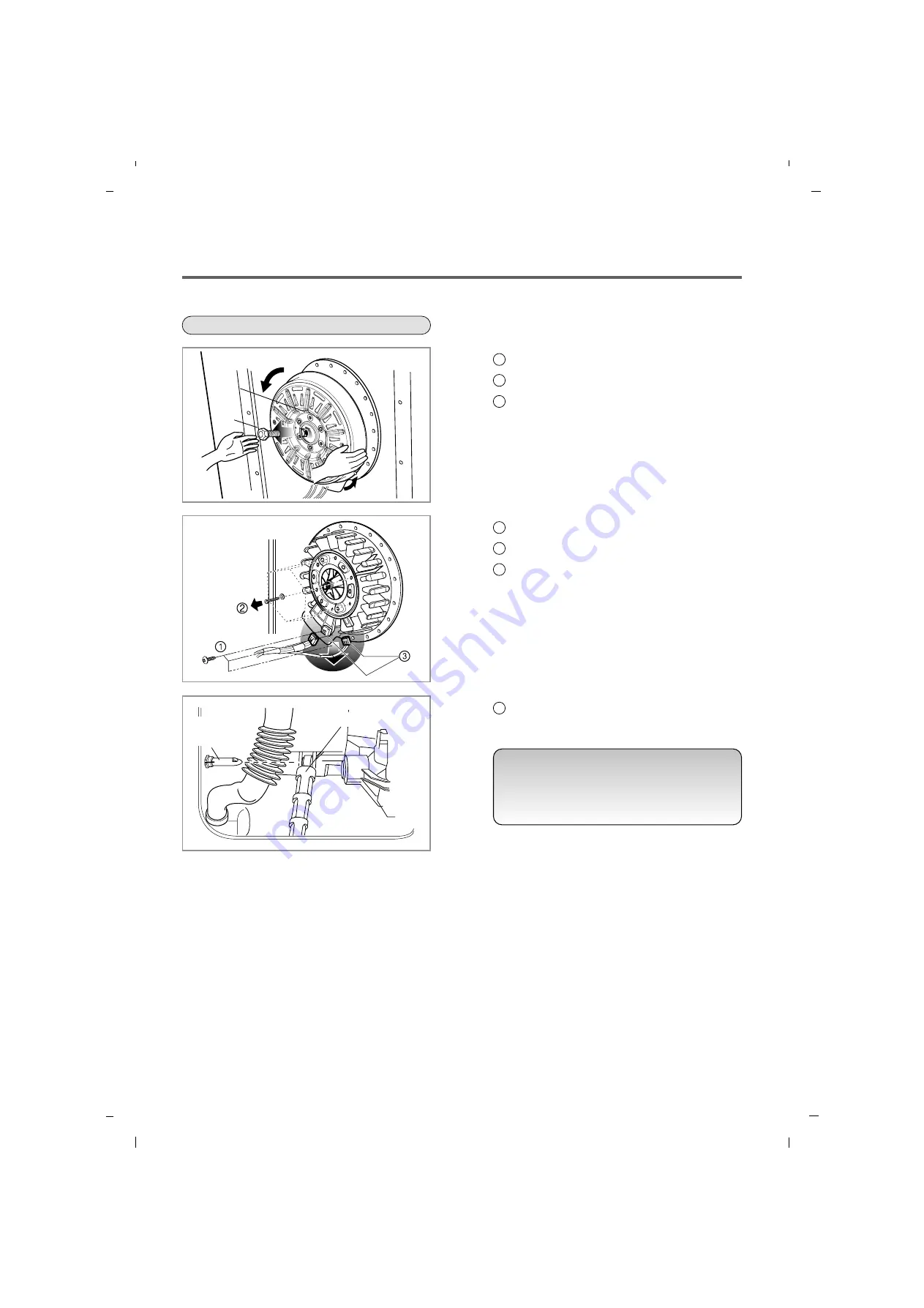
MOTOR/DAMPER
આ
NOTE
• If you pull the dampers apart, the must be
replaced. If you do not separate them, they
can be re-used.
Bolt
Rotor
DAMPER
HINGE,
DAMPER
Disassemble the back cover.
Remove the bolt.
Pull out the rotor.
1
2
3
Unscrew the 2 screws from the tub bracket.
Remove the 6 bolts on the stator.
Unplug the 2 connectors from the stator.
1
2
3
Disassemble the damper hinges from the tub
and base.
1
Summary of Contents for 796.4107 31 Series
Page 2: ...JULY 2012 PRINTED IN KOREA P No MFL67307945 ...
Page 12: ...5 OPERATION 13 5 1 CONTROL PANEL FEATURES ...
Page 13: ...14 ...
Page 20: ...6 TROUBLESHOOTING SUMARTY 21 ...
Page 21: ...22 ...
Page 22: ...SPIN SPEED SOIL LEVEL WASH RINSE DELAYWASH 7 TEST MODE 23 ...
Page 26: ...27 DRAIN ERROR Wash Temp DELAY WASH SPIN SPEED SOIL LEVEL ...
Page 34: ... 0 1 2 3 3 4 35 ...
Page 37: ... 9 COMPONENT TESTING INFORMATION 38 ...
Page 44: ...45 9 5 INLET VALVE ASSEMBLY ...
Page 46: ...47 9 7 THERMISTOR ASSEMBLY Circuit in the MAIN PCB Wiring Diagram ...


