


1
PRINTED IN THE U.S.A. 0905
www.sears.com
PART NO. 185249-000
Sears, Roebuck and Co., Hoffman Estates, IL 60179 U.S.A
C3 Technology
®
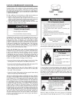
Gas Water Heaters meet
the new ANSI Z21.10.1 standard that deals
with the accidental or unintended ignition
of flammable vapors, such as those
emitted by gasoline.
Owner’s Manual
FOR POTABLE WATER HEATING ONLY.
NOT SUITABLE FOR SPACE HEATING.
NOT FOR USE IN MOBILE HOMES.
MODEL NO.
153.332040
40 Gallon Nat
153.332050
50 Gallon Nat
153.332060
40 Gallon LP
153.332070
50 Gallon LP
For Your Safety
AN ODORANT IS ADDED TO THE GAS USED BY THIS WATER HEATER.
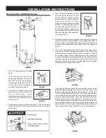
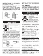
• Safety Instructions
• Installation
• Operation
• Care and Maintenance
• Troubleshooting
• Parts List
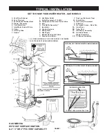
THE ECONOMIZER™ 6
GAS WATER HEATER
POWER VENTED GAS MODELS
WITH HOT SURFACE IGNITION
Si no puede leer o entender el inglés y necesita el manual instructivo
y/o etiquetas en español puede obtenerlos llamando al
1-800-821-2017. NO TRATE DE INSTALAR O OPERAR ESTE
CALENTADOR DE AGUA si no entiende la información en las etiquetas
o en el manual instructivo. No hacer caso de esta advertencia podría
resultar en la MUERTE O GRAVES LESIONES CORPORALES.
ADVERTENCIA
Summary of Contents for ECONOMIZER 6 153.332070
Page 3: ...3 SAFETY PRECAUTIONS ...


