


18
VENTING
The vent system must terminate so that proper clearances are
maintained as cited in local codes or the current edition of the National
Fuel Gas Code, ANSI Z223.1/NFPA 54, 7.3.4e and 7.8a,b, as follows:
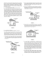
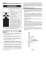
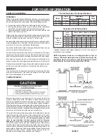
1. The exit terminals of a mechanical vent system shall be not less
than 7 feet (2.13 m) above grade when located adjacent to public
walkways, see Figure 23.
2. A venting system shall terminate at least 3 feet (91 cm) above any
forced air inlet located within 10 feet (3.1 m), see Figure 23.
3. The venting system shall terminate at least 4 feet (1.2 m) below, 4
feet (1.2 m) horizontally from or, 12 in. (30 cm) above any door,
window or gravity air inlet into any building.
The manufacturer also recommends that the vent termination should
not be installed closer than 3 feet (91 cm) from an inside corner of an
L shaped structure and not be less than 12 in. (30 cm) above grade.
The vent shall terminate a minimum of 12'' (30.5 cm) above expected
snowfall level to prevent blockage of vent termination, see Figure 23.
4. In cold climates, it is recommended that vent termination not be mounted
directly above or within 3 feet (91 cm) horizontally from an oil tank vent or
gas meter to avoid potential freeze-up from condensation, see Figure 23.
Plan the vent system layout so that proper clearances are maintained
from plumbing and wiring.
Vent pipes serving power vented appliances are classified by building
codes as “vent connectors”. Required clearances from combustible
materials must be provided in accordance with information in this manual
under FACTS TO CONSIDER ABOUT THE LOCATION and VENT
TERMINAL INSTALLATIONS, and with the National Fuel Gas Code and
local codes.
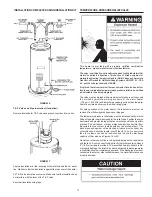
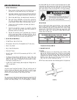
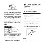
VENT TERMINAL INSTALLATION
1. After the point of termination has been determined, use the cover
plate as a template to mark the hole for the vent pipe to insert
through the wall. BEWARE OF CONCEALED WIRING AND PIPING
INSIDE OF WALL.
2. If the Vent Terminal is being installed on the outside of a finished
wall, it may be easier to mark both the inside and outside wall.
Align the holes by drilling a hole through the center of the template
from the inside through to the outside. The template can now be
positioned on the outside wall using the drilled hole as a centering
point for the template.
3. A) MASONRY SIDE WALLS
Chisel an opening approximately one half inch larger than the
marked circle.
B) WOODEN SIDE WALLS
Drill a pilot hole approximately one quarter inch outside of the
marked circle. This pilot hole is used as a starting point for a
saws-all or sabre saw blade. Cut around the marked circle staying
approximately one quarter inch outside of the line. (This will allow
the vent pipe to easily slide through the opening. The resulting
gap will be covered up by the vent terminal cover plates.) Repeat
this step on inside wall if necessary.
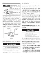
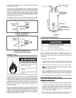
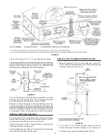
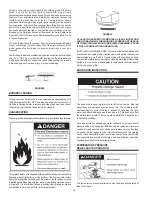
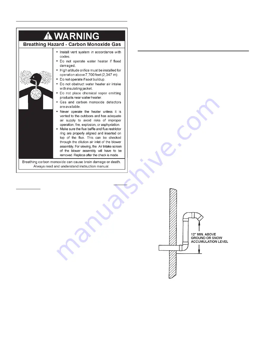
4. When the vent piping cannot pass through an outside wall at a
height greater than or equal to 12" above the ground (or above
snow accumulation level), then the installation can be modified as
shown below.
FIGURE 22.
Summary of Contents for ECONOMIZER 6 153.332070
Page 3: ...3 SAFETY PRECAUTIONS ...


