background image

26

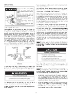
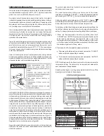
At least once a year a visual inspection should be made of the main
burner and the hot surface igniter assembly for proper flame
characteristics and ignition sequences. This can be done by removing
the Outer Door and viewing the main burner operation through the
Viewport on the Inner Door, see Figure 1. The main burner should
provide complete combustion of gas, ignite rapidly, give reasonably
quiet operation, and cause no excessive flame lifting from the burner
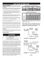
ports. If the proper flame characteristics are not evident (see Figure
28), make sure that the flow of combustion and ventilation air is not
blocked on the Air Intake Screen at the base of the water heater (see
Figure 29), the Lint screen on the blower assembly (see Figure 1), and
in the venting system.

You should also check for sooting. Soot is not normal and will impair
proper combustion. A visual inspection of the main burner and HSI
igniter assembly should also be done at least once a year, see
Figure 28.

Soot build-up indicates a problem that requires correction before further
use.  Turn “OFF” gas to water heater and leave off until repairs are
made, because failure to correct the cause of the sooting can result in
a fire causing death, serious injury, or property damage.

FIGURE 28.

BURNER CLEANING

In the event your burner or burner air openings require cleaning, turn
the blower switch to the “OFF” position and allow the burner to cool.
Call Sears Service Center to remove and clean the burner and correct
the problem that required the burner to be cleaned.
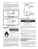
HOUSEKEEPING

Vacuum around base of water heater for dust, dirt, and lint on a regular basis.

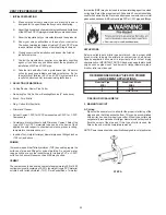
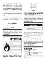
This water heater unit is supplied with a plastic Air Intake Screen that will
filter and prevent lint build-up on the bottom of the flame arrestor of this
heater. To prevent the lint build-up on the arrestor, the lint screen must be
installed on the Base Pan with the “arrows” pointing upwards as shown
in Figure 29. If the Air Intake Screen is missing from this heater, please
contact Sears Service Center for a replacement part.

FIGURE 29.

AT LEAST ONCE EVERY SIX MONTHS A VISUAL INSPECTION
SHOULD BE MADE OF THE AIR INTAKE SCREENS ON THE BASE
OF THE WATER HEATER AND THE BLOWER ASSEMBLY. CLEAN
IF LINT ACCUMULATIONS ARE NOTICED.

INSTALLED IN SUITABLE AREA: To insure sufficient ventilation and
combustion air supply, proper clearances from the water heater must
be maintained.  See “Facts to Consider About the Location” section.
Combustible materials such as clothing, cleaning materials, or flammable
liquids, etc. must not be placed against or adjacent to the water heater
which can cause a fire.

ANODE ROD INSPECTION

The anode rod is used to protect the tank from corrosion.  Most hot
water tanks are equipped with an anode rod.  The submerged rod
sacrifices itself to protect the tank.  Instead of corroding the tank,
water ions attack and eat away the anode rod.  This does not affect
the water’s taste or color.  The rod must be maintained to keep the tank
in operating condition.

Anode deterioration depends on water conductivity, not necessarily
water condition. A corroded or pitted anode rod indicates high water
conductivity and should be checked and/or replaced more often than
an anode rod that appears to be intact. Replacement of a depleted
anode rod can extend the life of your water heater. Inspection should
be conducted by a qualified technician, and at a minimum should be
checked annually after the warranty period.

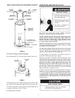
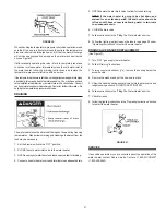
TEMPERATURE-PRESSURE
RELIEF VALVE OPERATION

The temperature-pressure relief valve must be manually operated at
least once a year.

Summary of Contents for ECONOMIZER 6 153.332070

Page 1: ...lon Nat 153 332060 40 Gallon LP 153 332070 50 Gallon LP For Your Safety ANODORANTISADDEDTOTHEGASUSEDBYTHISWATERHEATER Safety Instructions Installation Operation Care and Maintenance Troubleshooting Parts List THE ECONOMIZER 6 GAS WATER HEATER POWER VENTED GAS MODELS WITH HOT SURFACE IGNITION Si no puede leer o entender el inglés y necesita el manual instructivo y o etiquetas en español puede obten...

Page 2: ...u and others who install use or service this water heater All safety messages will generally tell you about the type of hazard what can happen if you do not follow the safety message and how to avoid the risk of injury IMPORTANT DEFINITIONS Gas Supplier The Natural Gas or Propane Utility or service who supplies gas for utilization by the gas burning appliances within this application The gas suppl...

Page 3: ...3 SAFETY PRECAUTIONS ...

Page 4: ...mbly Installation 15 16 Vent Connections to Blower Assembly 17 Venting and Installation 17 Condensation 17 Maximum Vent Lengths 17 Venting 18 Vent Terminal Installation 18 19 Vertical Vent Through Roof 19 Vertical Vent Termination Restrictions 19 Vent Pipe Preparation 20 21 OPERATING INSTRUCTIONS 22 23 Lighting and Operating Label 22 Temperature Regulation 23 FOR YOUR INFORMATION 24 25 Start Up Co...

Page 5: ...e manual that you must read and be aware of All warnings and all instructions are essential to the proper operation of the water heater and your safety Since we cannot put everything on the first few pages READ THE ENTIRE MANUAL BEFORE ATTEMPTINGTOINSTALLOROPERATETHEWATERHEATER 2 The installation must conform with these instructions and the local code authority having jurisdiction In the absence o...

Page 6: ... LESS AND AVAILABLE IN 28 711 mm DIAMETER FOR WATER HEATERS HAVING A DIAMETER 26 660 mm OR LESS Basic Tools You may or may not need all these tools depending on your type of installation These tools can be purchased at your local Sears Store Pipe Wrenches 2 14 356 mm Screwdriver Tin Snips 6 1 82 m Tape or Folding Ruler Garden Hose Drill Pipe Dope or Teflon Tape Additional Tools Needed When Sweat S...

Page 7: ...alve U Ground Joint Union V Drip Leg Sediment Trap W Drain Valve X Gas Valve Thermostat Y Drain Pan Z Air Intake Screen Base Pan AA Inner Door BB Outer Door CC HSI Burner Assembly DD Air Intake Screen Blower Assembly EE FV Sensor Assembly NATURAL HOT SURFACE IGNITER MAIN BURNER HOT SURFACE IGNITOR SENSOR PROPANE HOT SURFACE IGNITER MAIN BURNER TEMPERATURE INDICATORS TEMPERATUREADJUSTMENT BUTTONS H...

Page 8: ...can be lifted off after any screw or other attached devices are removed Make sure existing vent complies with maximum and minimum vent lengths on page17 6 If you have copper piping to the water heater the two copper water pipes can be cut with a hacksaw approximately four inches away from where they connect to the water heater see Figure 6 This will avoid cutting off pipes too short Additional cut...

Page 9: ...ger an alarm or turn off the incoming water to the water heater when leakage is detected Sensors mounted in the drain pan that turn off the water supply to the entire home when water is detected in the drain pan Water supply shut off devices that activate based on the water pressure differential between the cold water and hot water pipes connected to the water heater Devices that will turn off the...

Page 10: ...r meets or exceeds the National Appliance Energy Conservation Act standards with respect to insulation and standby loss requirements making an insulation blanket unnecessary Should you choose to apply an insulation blanket to this heater you should follow these instructions For identification of components mentioned below see Figure 1 Failure to follow these instructions can restrict the air flow ...

Page 11: ...re inch per 4 000 Btu per hour 5 5 cm2 kW of total input rating of all equipment in the enclosure see Figure 12 FIGURE12 2 When communicating with the outdoors through vertical ducts each opening shall have a minimum free area of 1 square inch per 4 000 Btu per hour 5 5 cm2 kW of total input rating of all equipment in the enclosure see Figure 13 3 When communicating with the outdoors through horiz...

Page 12: ...r tubing to an adapter before attaching the adapter to the cold water inlet connection Do not solder the cold water supply line directly to the cold water inlet It will harm the dip tube and damage the tank Look at the top cover of the water heater The water outlet is marked HOT Put two or three turns of teflon tape around the threaded end of the threaded to sweat coupling and around both ends of ...

Page 13: ...pressure not to exceed the marked hydrostatic working pressure of the water heater 150 psi 1 035 kPa and a discharge capacity not less than the water heater input rate as shown on the model rating plate For safe operation of the water heater the relief valve must not be removed from its designated opening nor plugged The temperature pressure relief valve must be installed directly into the fitting...

Page 14: ...plosion from leaking gas If the main gas line Shut off serving all gas appliances is used also turn off the gas at each appliance Leave all gas appliances shut off until the water heater installation is complete A gas line of sufficient size must be run to the water heater Consult thecurrenteditionofNationalFuelGasCodeANSIZ223 1 NFPA54and your gas supplier concerning pipe size There must be A read...

Page 15: ...ll be either a tee fitting with a capped nipple in the bottom outlet or other device recognized as an effective sediment trap If a tee fitting is used it shall be installed in conformance with one of the methods of installation shown in Figures 18 and 19 FIGURE20 FILLING THE WATER HEATER Never use this water heater unless it is completely full of water To prevent damage to the tank the tank must b...

Page 16: ...heater operates on 110 120 Vac therefore a grounded outlet must be within reach of the six 6 foot 1 8 m flexible power cord supplied with the unit see Figure 1 The power cord supplied may be used only where local codes permit If local codes do not permit the use of a flexible power supply cord a Make sure the unit is unplugged from wall outlet Remove screws and open panel on front of control box b...

Page 17: ... vent pipe needs to be installed in the rubber boot for proper connection of the 2 to 3 bell reducer Thatlengthcanbetheminimumlengthrequiredfortheconnection If 4 pipe is to be used then a 3 to 4 bell reducer is recommended Figure 21 shows the recommended location for the bell reducer If the bell reducer is located at the rubber boot on the blower assembly then a short section of 3 vent pipe needs ...

Page 18: ...s Required clearances from combustible materialsmustbeprovidedinaccordancewithinformationinthismanual under FACTS TO CONSIDER ABOUT THE LOCATION and VENT TERMINALINSTALLATIONS and with the National Fuel Gas Code and local codes VENT TERMINAL INSTALLATION 1 After the point of termination has been determined use the cover plate as a template to mark the hole for the vent pipe to insert throughthewal...

Page 19: ... wall flange is supplied for decorative purposes only and is not a requirement for the vent termination if not needed by the installer VERTICAL VENT THROUGH ROOF This unit is approved for venting through the roof with the type vent terminal that is included with the unit A proper flashing or BOOT should be used to seal the pipe where it exits the roof The total vent system should not exceed that w...

Page 20: ...hes 15 2 cm and above PRIMER It is recommended that Tetrahydrofuran THF be used to prepare the surfaces of pipe and fittings for solvent welding Do not use water rags gasoline or any other substitutes for cleaning PVC or CPVC surfaces Achemical cleaner such as MEK may be used CEMENT The cement should be a bodied cement of approximately 500 to 1600 centipoise viscosity containing 10 20 by weight vi...

Page 21: ...tance and make a second mark as the primer and cement will most likely destroy your first one Apply primer to the surface of the pipe and fitting socket with a natural bristlebrush ThisprocesssoftensandpreparesthePVCorCPVCfor thesolventcementingstep Movequicklyandwithouthesitationtothe cementingprocedurewhilethesurfacesarestillwetwithprimer E Application of solvent cement Applythesolventcementeven...

Page 22: ...uttons together and holding for 1 second Then press the COOLER button until the WARM indicator light appears 2 Set the ON OFF switch on the blower control box to the OFF position 3 Turn off all electric power to the appliance if service is to be performed BEFORE OPERATING ENTIRE SYSTEM MUST BE FILLED WITH WATERANDAIR PURGED FROMALL LINES 1 STOP Read the safety information above on this label 2 Set...

Page 23: ...e shall be used at the hot water taps used by these people or at the water heater Mixing valves are available at plumbing supply or hardware stores see Figure 15 Follow manufacturer s instructions for installation of the valves Before changing the factory setting on the thermostat read the Temperature Regulation section in this manual see Figure 26 Never allow small children to use a hot water tap...

Page 24: ...ssure frequent cut offs the effects of water hammer among others have installed devices such as pressure reducing valves check valves back flow preventers etc to control these types of problems When these devices are not equipped with an internal by pass and no other measures are taken the devices cause the water system to be closed As water is heated it expands thermal expansion and closed system...

Page 25: ... faucet located farthest away be opened for several minutes before any electrical appliances which are connected to the hot water system are used such as a dishwasher or washing machine If hydrogen gas is present there will probably be an unusual sound similar to air escaping through the pipe as the hot water faucet is opened There must be no smoking or open flame near the faucet at the time it is...

Page 26: ...en that will filter and prevent lint build up on the bottom of the flame arrestor of this heater To prevent the lint build up on the arrestor the lint screen must be installed on the Base Pan with the arrows pointing upwards as shown in Figure 29 If theAir Intake Screen is missing from this heater please contact Sears Service Center for a replacement part FIGURE29 AT LEAST ONCE EVERY SIX MONTHS A ...

Page 27: ...ter inlet valve to the water heater 3 OPENanearbyhotwaterfaucetandleaveopentoallowfor draining 4 Connectahosetothedrainvalveandterminatetoanadequatedrain 5 OPEN the water heater drain valve to allow for tank draining NOTE If the water heater is going to be shut down and drained for an extended period the drain valve should be left open with hose connected allowing water to terminate to an adequate...

Page 28: ...valve may be leaking at the tank fitting H Combustion products contain water vapor which can condense on the cooler surfaces of the tank Droplets form and drip onto the burner or run on the floor This is common at the time of start up after installation and when incoming water is cold I Water in the water heater bottom or on the floor may be from condensation looseconnections orthereliefvalve DONO...

Page 29: ...ce ignitor not positioned correctly 3 Low voltage to the water heater 4 Electric polarity to unit is incorrect test and correct Problem in the gas valve driver circuit 1 Turn power to the water heater off for 10 seconds and the back on 2 Replace gas control valve Problem with the internal circuit 1 Turn power to the water heater off for 10 seconds and then back on 2 Replace gas control valve Probl...

Page 30: ...30 These guidelines should be utilized by a qualified service agent When calling for service notify the service agent that this is a Flammable Vapor Ignition Resistant Product TROUBLESHOOTING GUIDELINES ...

Page 31: ...4316 9004316 9004316 9004316 11 Air Intake Screen Base Pan 9003406 9003406 9003406 9003406 12 InletTube 9003447 9002547 9003447 9002547 13 Gas Control Valve 9005962 9005962 9005963 9005963 14 Drain Valve 9002402 9002402 9002402 9002402 15 Drain Valve Washer 9001584 9001584 9001584 9001584 16 Outer Door 9005966 9005966 9005966 9005966 17 Anode Rod 9003972 9003891 9003972 9003891 18 Temperature Pres...

Page 32: ...help prolong the life of your new purchase for years to come Purchase your Master Protection Agreement today Some limitations and exclusions apply For prices and additional information call 1 800 827 6655 SEARSINSTALLATIONSERVICE For Sears professional installation of home appliances garage door openers water heaters and other major home items in the U S A call 1 800 4 MY HOME For in home major br...

Reviews: